Transitioning Photospheres

Difficulty Level: Intermediate
Coding Knowledge Required: Beginner
Time to Complete: 60-90 minutes
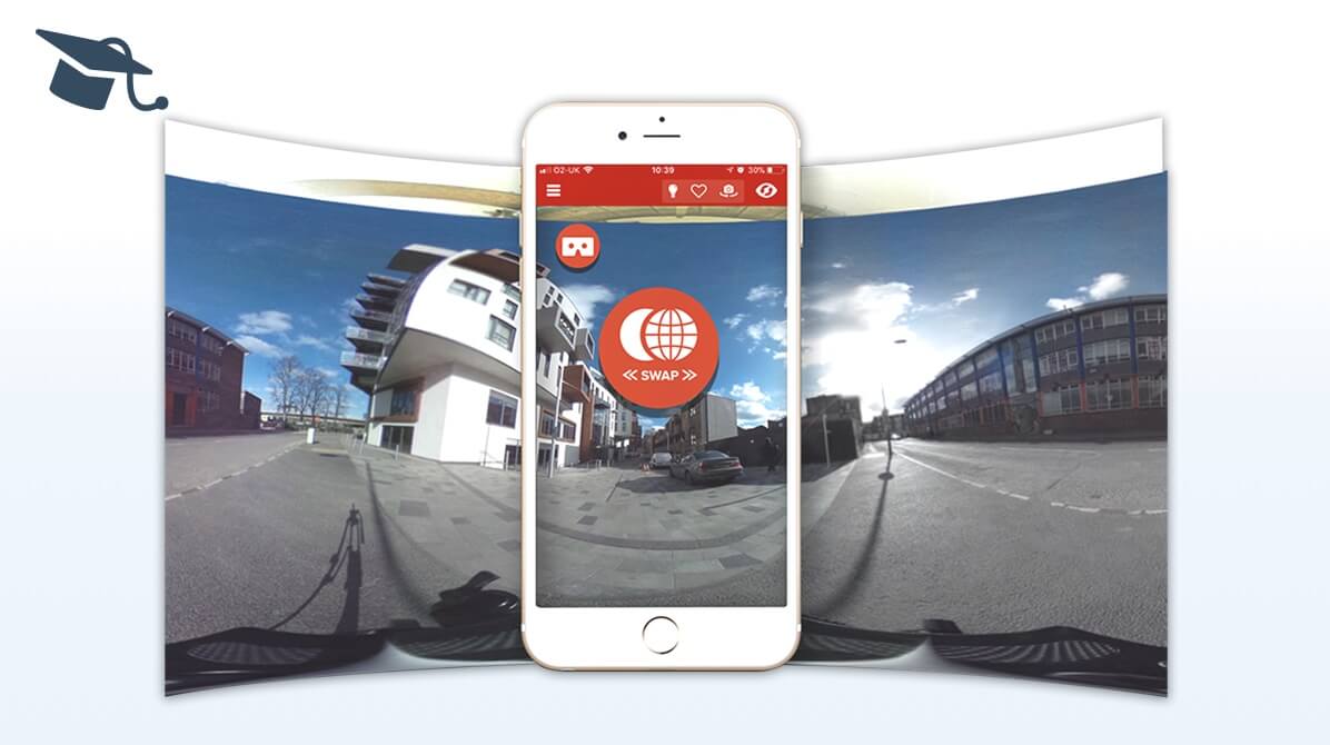
In this experience, you will build two separate photospheres, and learn how to create the transitions between them. You will also learn how to switch from standard mobile view to headset view, which can be experienced in a cardboard headset such as Google Cardboard. In the headset view, you will use a raycaster to transition between the photospheres. Make sure to scan the zapcode above for a sneak peak into what you are about to build.
Here is how the experience works: At any time, you can click on the headset icon in the corner to switch from the standard to headset view.
- In standard view (AR mode): tap the red “transition-icon” to travel to the other sphere.
- In headset view (VR mode): position the crosshair on the red “transition-icon” and wait for 4 seconds to move to the other sphere. If you want to stay in the current sphere, stop pointing at the red icon with the crosshair.
We first introduced the concept of photo spheres in the following tutorial: Step-by-step Interactive 360 Panorama. It’s recommended that you take a look at that project before following along this one, however, it is possible to complete this without doing so.
We’ve split this tutorial into 6 parts so that you can take a break after completing a part and before starting the next one. We also recommend that you preview the project at the end of each part and check everything works as intended.
Step by Step
Part 1: Setting up the project
In this part, we will create our zapcode and Studio project, as well as import all the assets needed for the experience.
1. Create a new Studio zapcode
Enter your my.zap.works account and click the ‘Make a New Zapcode’ button in the top left. Give your code a name, choose between either a circle or lozenge style and select ‘Studio’ as your tool. Widgets and Designer codes will not work for this tutorial.
2. Create a new project in ZapWorks Studio
Open ZapWorks Studio and create a ‘New Project’. Choose to start with a ‘Blank’ template and give your project a name, e.g. “Photo Spheres AR VR” then click ‘Create’.
If you are yet to download ZapWorks Studio, you can do so by following this link here.
3. Download the asset pack
Click here to download a zip file containing all the assets we’ll need for this experience.
After downloading the assets, unzip the file.
4. Import assets into the Media Library
Import all assets from the unzipped ‘assets’ folder into the Media Library.
5. Add a photosphere object in the Media Library
Click on the ‘+’ icon next to the Media Library and select ‘Photo Sphere’.
Part 2: Setting up the scene
In this part, we will add all the assets needed for the experience to the Hierarchy. We will also add new objects and create groups to make sure the Hierarchy is as clear and tidy as possible.
Throughout the project, we advise you to rename the objects added to the Hierarchy to make it easier to work with.
6. Create a group for the entire content of the experience
In the Hierarchy, right click on the ‘root’ node, select ‘New > Group’ and name it “content”.
This group will contain all the objects needed for the experience except the accelerometer. This ‘content’ group will allow you to easily hide/show the content of the experience later on in the project.
7. Create an Attitude Orient node
In the Hierarchy, right click on the ‘content’ node just created, select ‘New > Transforms > AttitudeOrient’ and call it “attitudeOrient”.
When an AttitudeOrient node is added to the Hierarchy its ‘relativeTo’ property is automatically set to ‘Z.camera’. This ensures that the node is centered on the screen. As a consequence, any objects placed inside the attitudeOrient node will be oriented around the camera. For more information about the attitude orient object, please see the Gyro-oriented Environments article.

8. Add the photospheres
Next, we will create a group for the two photo spheres. Inside this group, there will be one group per photosphere, with each group containing all the assets shown in the photosphere.
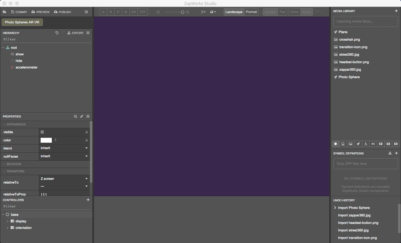
8.1) Create a group for the photo spheres
In the Hierarchy, right click on the ‘attitudeOrient’ node, select ‘New > Group’ and call it “sphereGroup”.
Right click on ‘sphereGroup’, select ‘New > Group’ and call it “sphere1”.
Again, right click on ‘sphereGroup’, select ‘New > Group’ and call it “sphere2”. Make sure ‘sphere2’ is positioned below ‘sphere1’ in the Hierarchy.
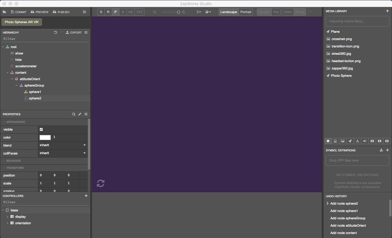
8.2) Add the first photosphere to the scene
Drag the ‘Photo Sphere’ object from the Media Library into the Hierarchy, inside the 'sphereGroup > sphere1’ group. Rename it to “Photo Sphere1”.
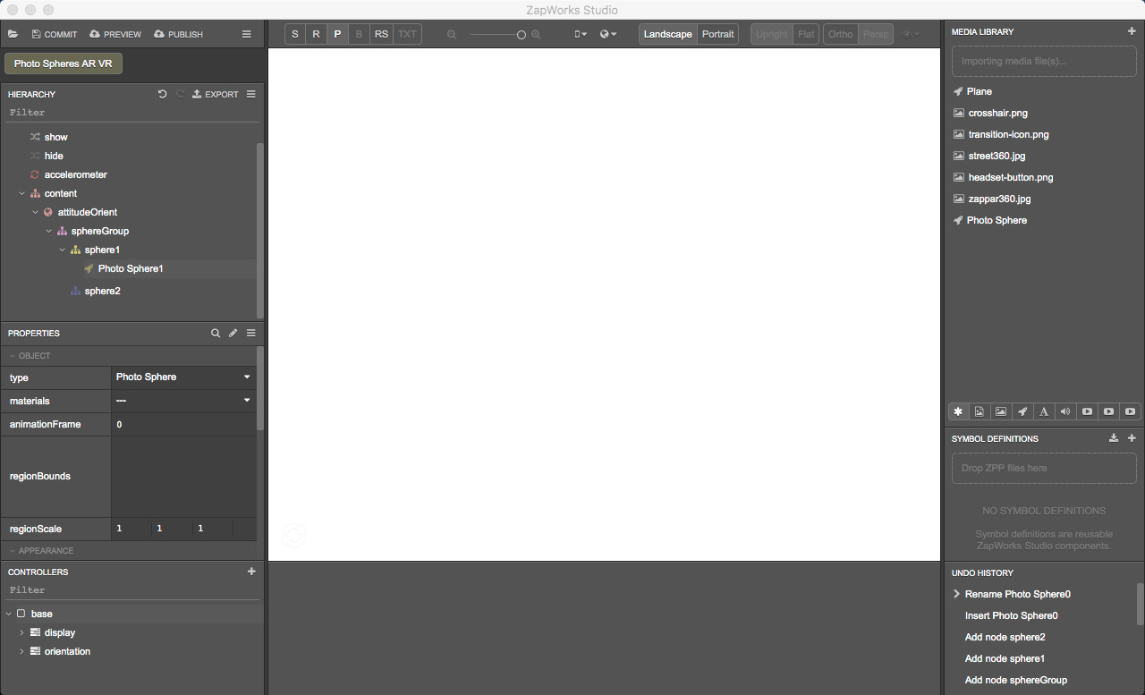
8.3) Set the photosphere’s properties
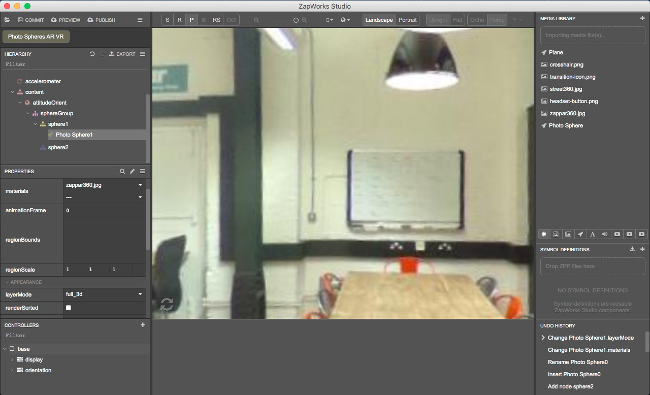
Making sure ‘Photo Sphere1’ is selected in the Hierarchy, in the Properties panel, set:
- The ‘materials’ property in the 'Object’ section to ‘zappar360.jpg’;
- The ‘layerMode’ property in the 'Appearance’ section to “full_3d”.
An object with a full_3d layerMode will appear over objects earlier in the hierarchy except those with full_3d layering that are spatially positioned closer to the camera. To find out more about the different layerMode types, see the Render Order documentation.
You can click and drag on the widget in the bottom left corner of the 3D view to move within the sphere. However, make sure you start clicking on the widget or you might accidentally change the scale or position of the photosphere. You may also notice giant red, blue and green dots: these are the transform arrows. They appear really big because the camera is in [0,0,0], overlapping the center of the photosphere currently selected.
8.4) Add the second photosphere to the scene
Drag the ‘Photo Sphere’ object from the Media Library into the Hierarchy, inside the 'sphereGroup > sphere2’ group. Rename it to “Photo Sphere2”.
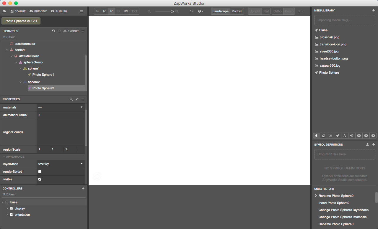
8.5) Set the second photosphere’s properties
Check ‘Photo Sphere2’ is still selected in the Hierarchy and in the Properties panel, set:
- The ‘materials’ property in the 'Object’ section to ‘street360.jpg’;
- The ‘position’ property in the 'Transform’ section to (2,0,0).
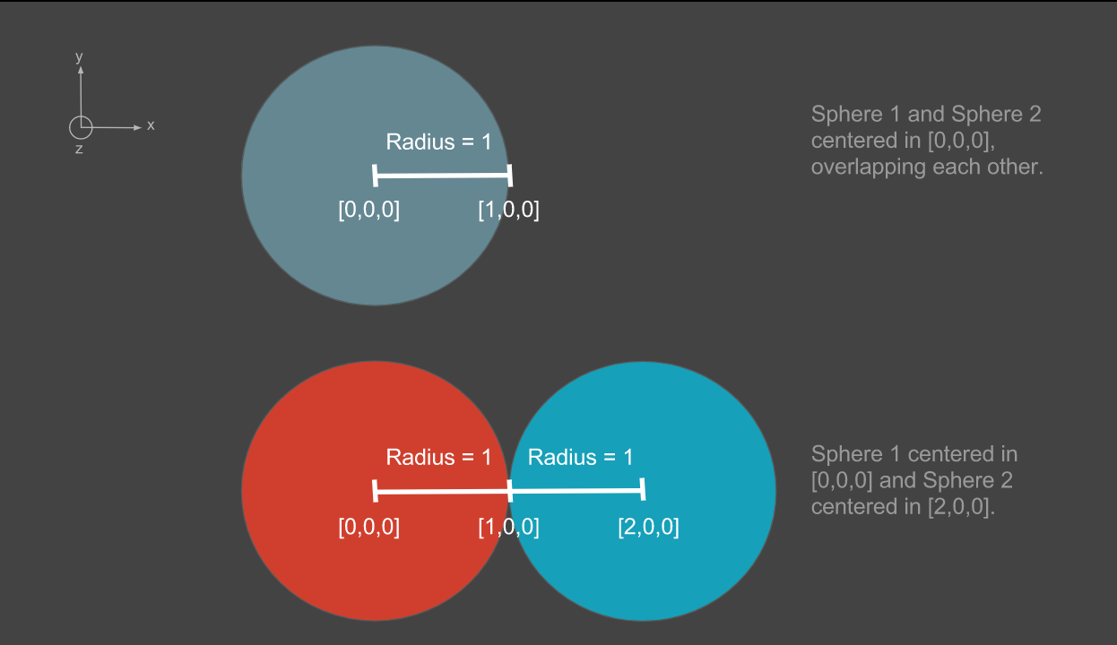
When added to the scene, a photosphere has a radius of 1 and a center that is placed in [0,0,0] by default. To make sure the two spheres are not overlapping each other, you will need to move the center of the second sphere from at least 2 (radius of first sphere + radius of the second sphere) along the X, Y or Z axis. We’ve decided to move the center of the second photosphere from 2 along the X axis here.
Although you’ve moved the second sphere away from the first one in the space, you can still see it when moving within the first sphere using the widget in the bottom left corner of the 3D view. This is because ‘sphere2’ is below ‘sphere1’ in the Hierarchy and because its ‘layerMode’ property is set to ‘overlay’.
An object with a ‘layerMode’ set to ‘overlay’ will appear over all objects earlier in the hierarchy regardless of their 3D positions in the camera space. Please see the Render Order article to learn more about this concept.
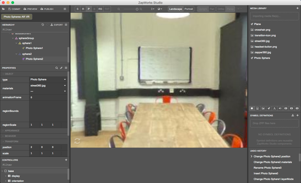
Make sure ‘Photo Sphere2’ is still selected in the Hierarchy and, in the Properties panel, set the ‘layerMode’ property in the 'Appearance’ section to “full_3d”.
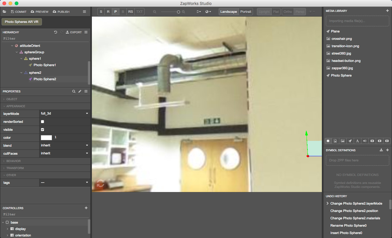
You should no longer be able to see the second photosphere as it has vanished behind the first one.
8.6) Add the icon to move from sphere 1 to sphere 2
We’ll now add the icons, which will act as buttons to transfer from one sphere to the other.
Drag the ‘transition-icon.png’ asset from the Media Library into the Hierarchy, inside the 'sphereGroup > sphere1’ node and below ‘Photo Sphere1’. Rename it to ‘transition-icon.png1’.
Making sure ‘transition-icon.png1’ is selected in the Hierarchy and in the Properties panel, change:
- The ‘layerMode’ property in the 'Appearance’ section to “full_3d”,
- The ‘position’ property in the 'Transform’ section to (0.1, 0.25, -0.7),
- The ‘scale’ property in the 'Transform’ section to (0.15, 0.15, 0).
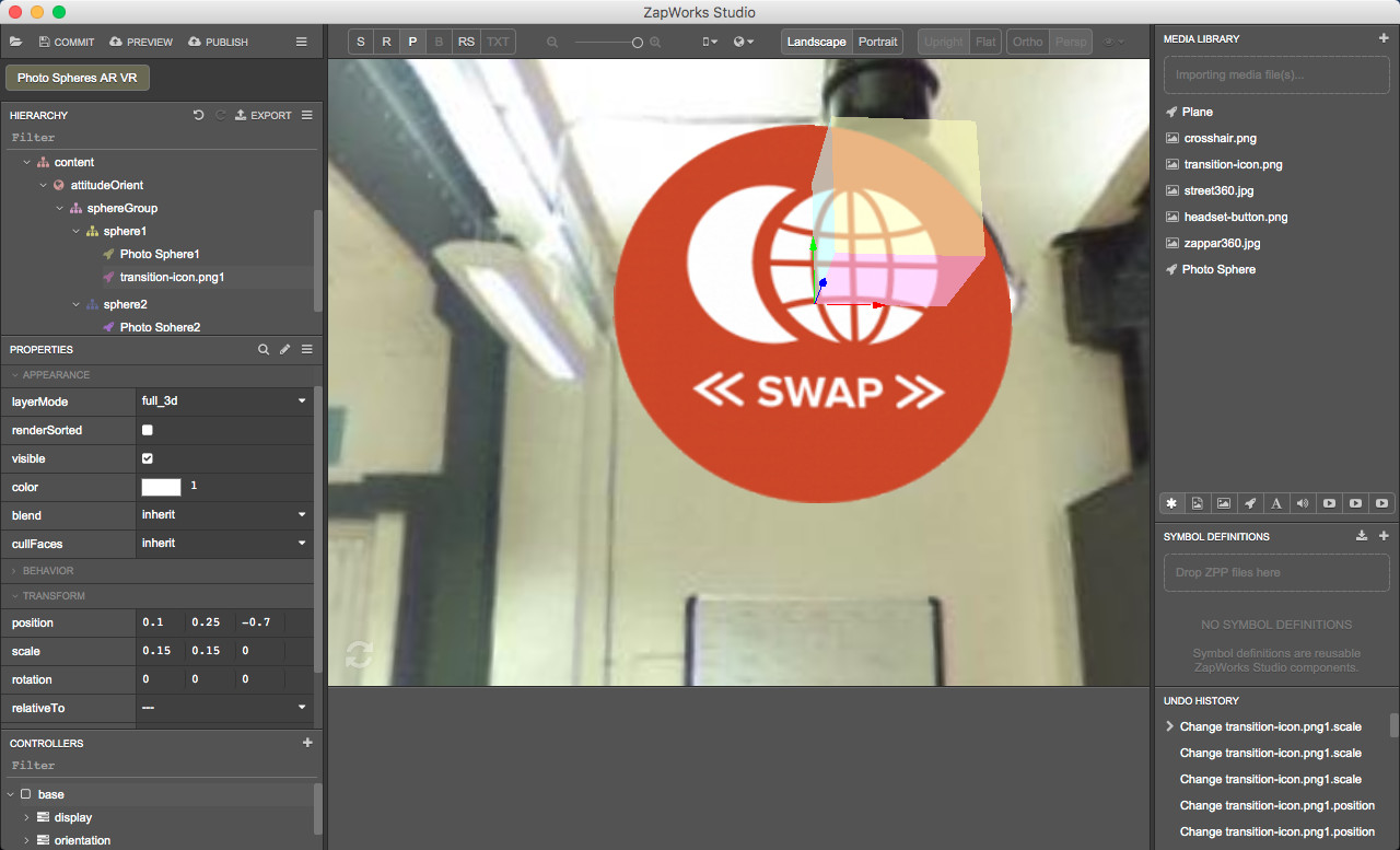
Feel free to move within the sphere and locate the icon which is above the table in the picture. You can use the widget in the bottom left of the 3D view to do so.
8.7) Add the icon to move from sphere 2 to sphere 1
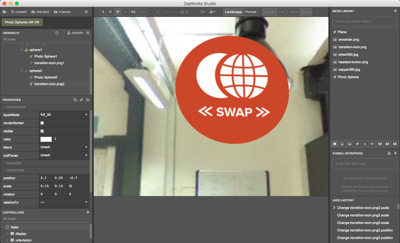
Again, drag the ‘transition-icon.png’ asset from the Media Library into the Hierarchy, inside 'sphereGroup > sphere2’ below the ‘Photo Sphere 2’. Rename it to ‘transition-icon.png2’.
Making sure ‘transition-icon.png2’ is selected in the Hierarchy, in the Properties panel, change:
- The ‘layerMode’ property in the 'Appearance’ section to “full_3d”,
- The ‘position’ property in the 'Transform’ section to (2.1, 0.25, -0.7),
- The ‘scale’ property in the 'Transform’ section to (0.15, 0.15, 0).
9. Add a headsetManager object to the scene
The headsetManager object will allow you to launch the experience in headset view.
The HeadsetManager is responsible for Zappar’s support for VR/AR headsets. For more information about it, see the Using HeadsetManager article.
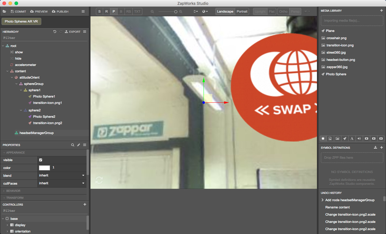
9.1) Create a group for the headsetManager
At this point, since the Hierarchy contains many objects, you can use the arrows next to the nodes to collapse groups in order to see more of less of the Hierarchy.
In the Hierarchy, right click on the ‘content’ node, select ‘New > Group’ and call it ‘headsetManagerGroup’.
9.2) Add a headsetManager to the group
Right click on the ‘headsetManagerGroup’, select ‘New > HeadsetManager’ and rename it to ‘headsetManager’.
9.3) Add the headset button to the group
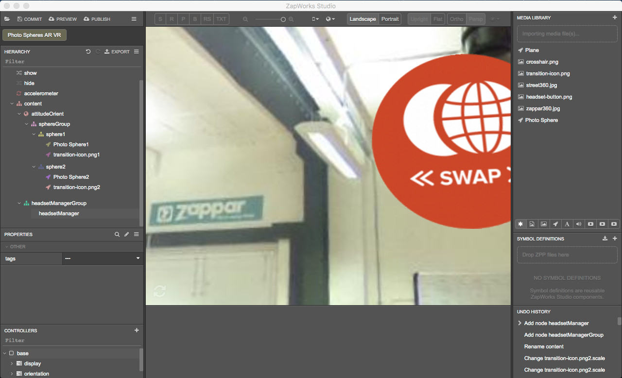
Drag ‘headset-button.png’ from the Media Library to the Hierarchy, into the ‘headsetManagerGroup’ (before or after the ‘headsetManager’ node).
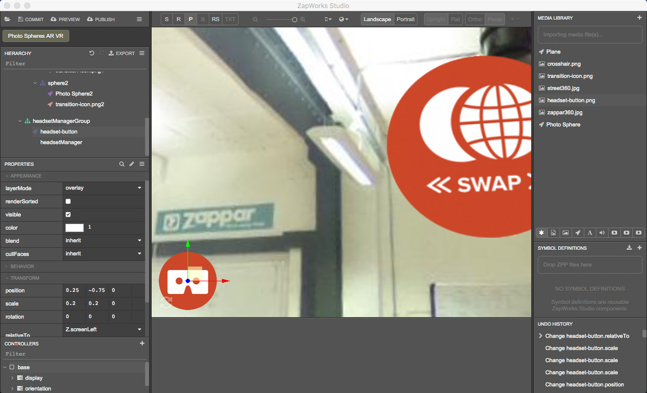
Rename it to ‘headset-button’ and in the Properties panel make sure the ‘layerMode’ property in the 'Appearance’ section is set to ‘overlay’ and change:
- The ‘position’ property in the 'Transform’ section to (0.25, -0.75, 0),
- The ‘scale’ property in the 'Transform’ section to (0.2, 0.2, 0),
- The ‘relativeTo’ property in the 'Transform’ section to ‘Z.screenLeft’.
The ‘relativeTo’ property of the icon is set to ‘Z.screenLeft’ so that the icon appears on the left-hand side of the device. Please, see the UI Coordinate Systems article for more information.
It’s important to make sure the ‘layerMode’ property is set to ‘overlay’ as this will make the icon constantly visible on the screen. The icon object will appear over all objects earlier in the hierarchy regardless of their 3D positions in the camer
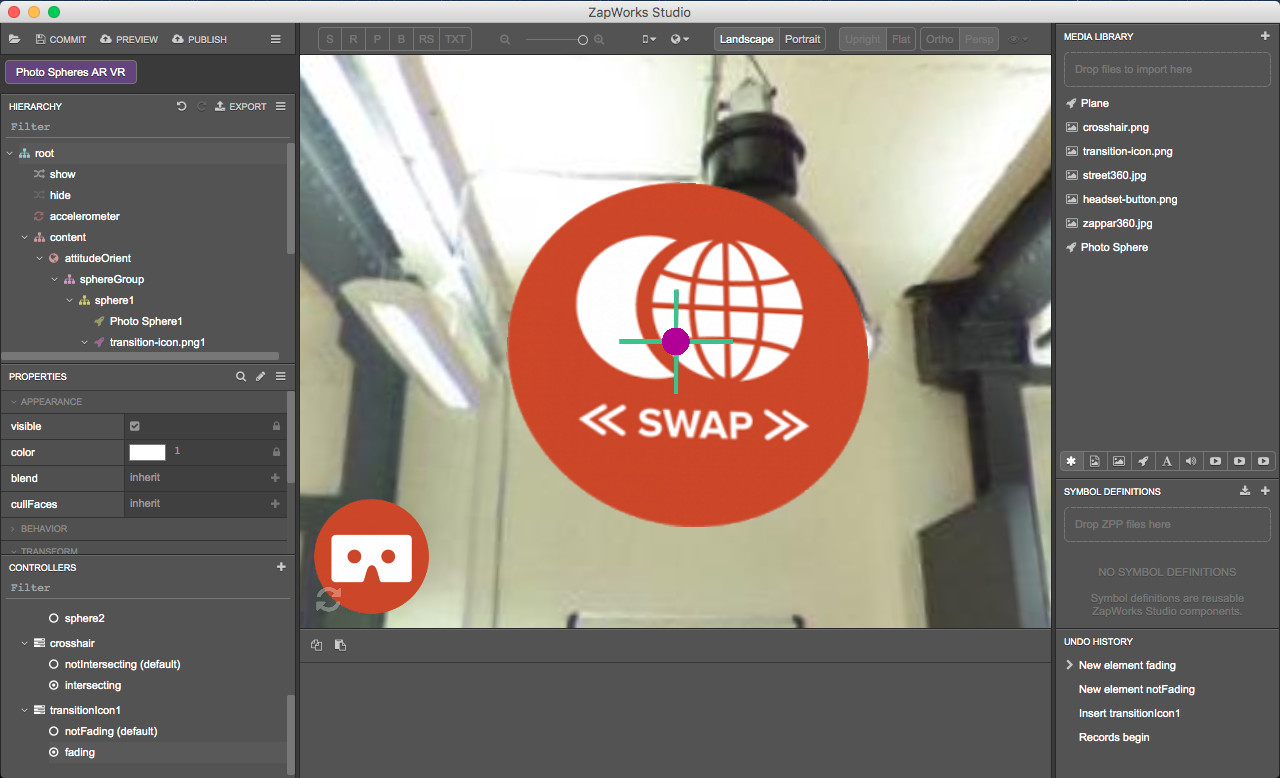
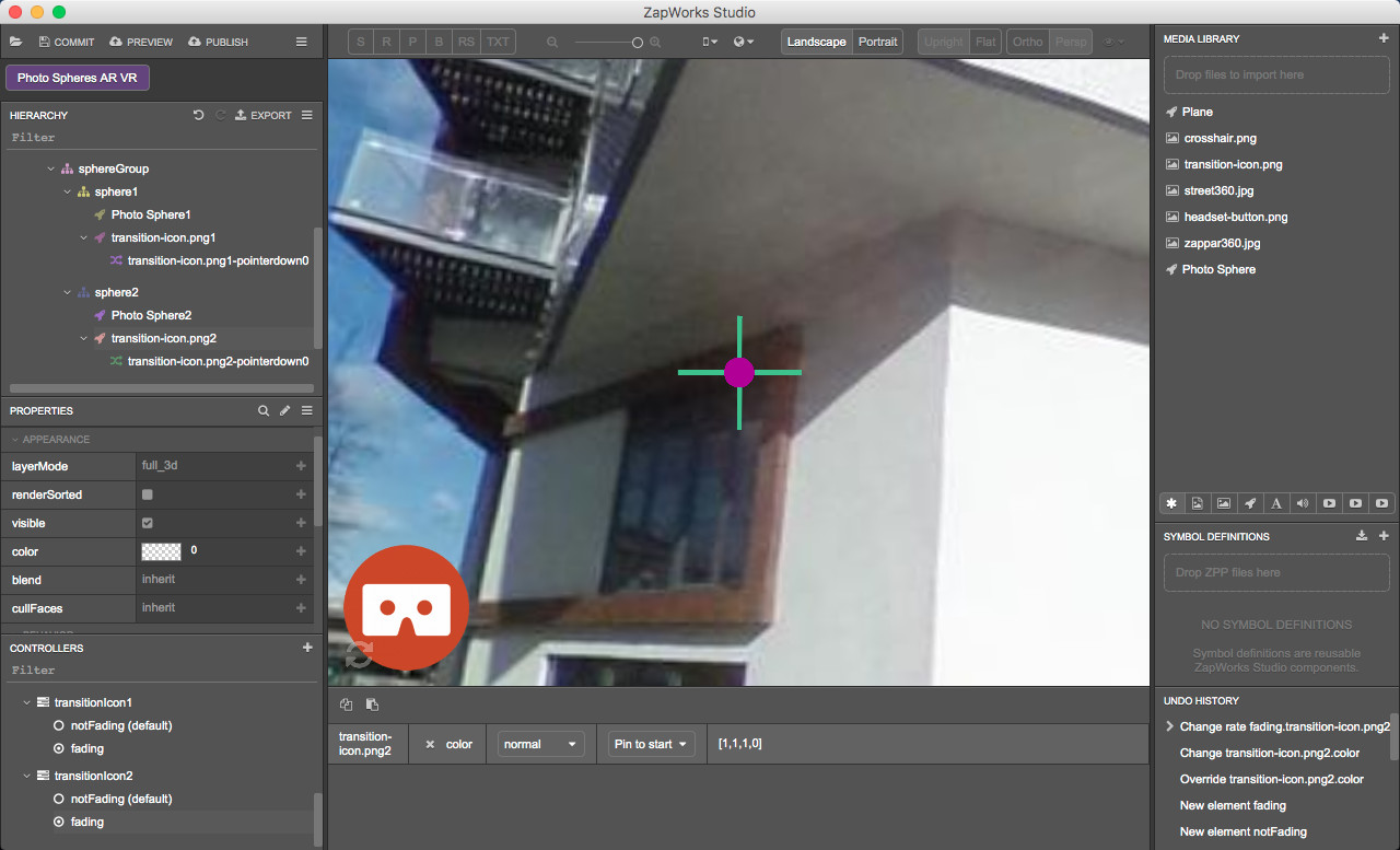
10. Preview the experience Click on the “Preview’ button and scan the zapcode with your device to see what the experience looks like at this stage of the project.
At this early stage, you should be able to move within ‘Photo Sphere1’ and see the transition icon above the table in the picture. You should also see the headset button attached to the left hand side of the screen when the device is held in landscape orientation.
Part 3: Adjusting the opening transition
In designing any AR/VR experience, it is important to keep the end user front of mind. In our opening transition, we are going to add a fade intro as soon as the experience is loaded. This will be more immersive and rewarding than having the photosphere suddenly appear.
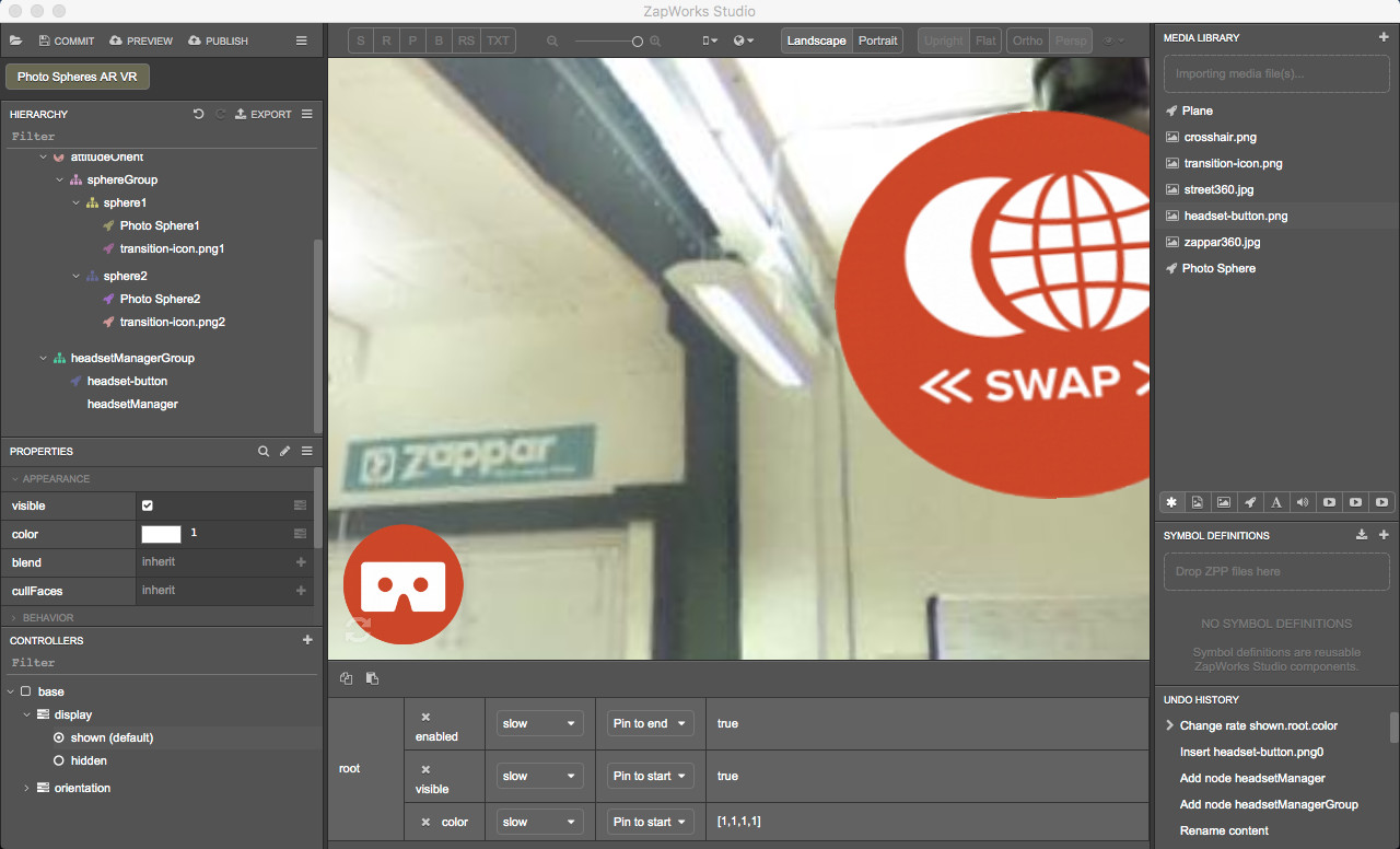
11. Set the content to fade in slowly
In the Controllers panel, unfold the ‘Display’ controller and click on the ‘shown’ state. In the state panel, change the transition speed from ‘fast’ to ‘slow’ for the root’s ‘enabled’, ‘visible’ and ‘color’ properties.
There is no need to activate this state since it is activated by default in the ‘show’ script.
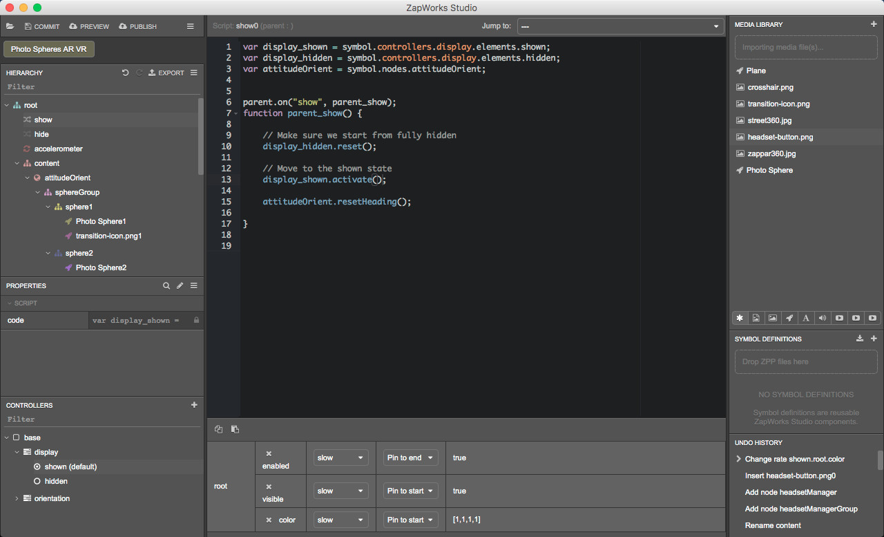
12. Reset the headset heading
When an AttitudeOrient node is used, the heading (i.e. north, east, south, west) will depend on the direction the user is facing. It’s often useful to reset the heading of the AttitudeOrient node so that the user faces down the negative Z axis. This is used here to ensure that the user is presented with a consistent view at the start of the experience.
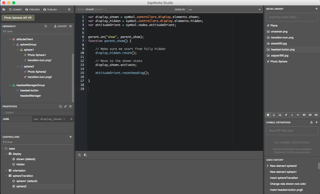
Drag the ‘attitudeOrient’ node from the Hierarchy into the ‘show’ script, outside and before the function. When releasing select ‘Insert local variable’.
In the Hierarchy, select the show script to open it. Within the function, add the following command:
< nameofvariable >.resetHeading();
If you followed the naming suggested in the previous steps, it should be: attitudeOrient.resetHeading();
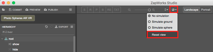
To see what part of the sphere you’ll face when launching the experience, you can select the ‘root’ node in the Hierarchy and click on the “earth” logo at the top of the 3D view and select “Reset view”.
13. Preview the experience
Click on the “Preview’ button and scan the zapcode with your device.
After scanning the zapcode, when the experience is unlocked, the content - which has not changed since the end of the previous part - should fade in.
Part 4: Setting up functionality in the standard view
Now that all the elements needed for the experience are in the scene, we need to define and set up the functionality for the standard view as well as for the headset view.
In this part of the project, we will focus on the standard AR view. Here is what we are looking to achieve:
- When the user is in a sphere, they can move to the other sphere by pressing the ‘transition-icon’ icon, which can then be considered as a button.
- At any time, the user can press the headset icon to switch from the standard to headset view. Also, the headset icon’s orientation will follow the device’s orientation.
14. Add states to show the inside of the spheres
In the Controllers panel, click on the ‘+’ icon, select ‘New Controller’ and call it “sphereTransition”.
14.1) Add states to the controller
Right-click on the ‘sphereTransition’ controller, select ‘New State’ and call it “sphere1”.
Again, right click on the ‘sphereTransition’ controller, select ‘New State’ and call it “sphere2”.
14.2) Add a property to the controller
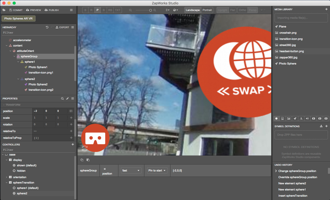
In the Controllers panel, with the ‘sphere2’ state still selected, in the Hierarchy select ‘sphereGroup’.
In the Properties panel, click on the ‘+’ icon next to the ‘position’ property in the 'Transform’ section (this will add the property to the ‘sphereTransition’ controller). Set the ‘position’ property to (-2,0,0).
Note: You should now see the center of sphere 2 since positioning the ‘sphereGroup’ node in [-2,0,0] moved the center of sphere 2 from [2,0,0] to [0,0,0], where the camera is located.
15. Set the transition icons to move from one sphere to the other
15.1) Set the icon to move from sphere 1 to sphere 2
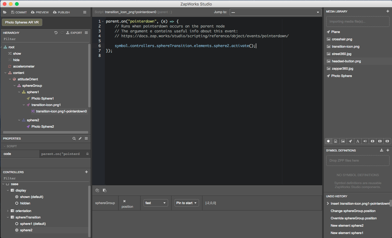
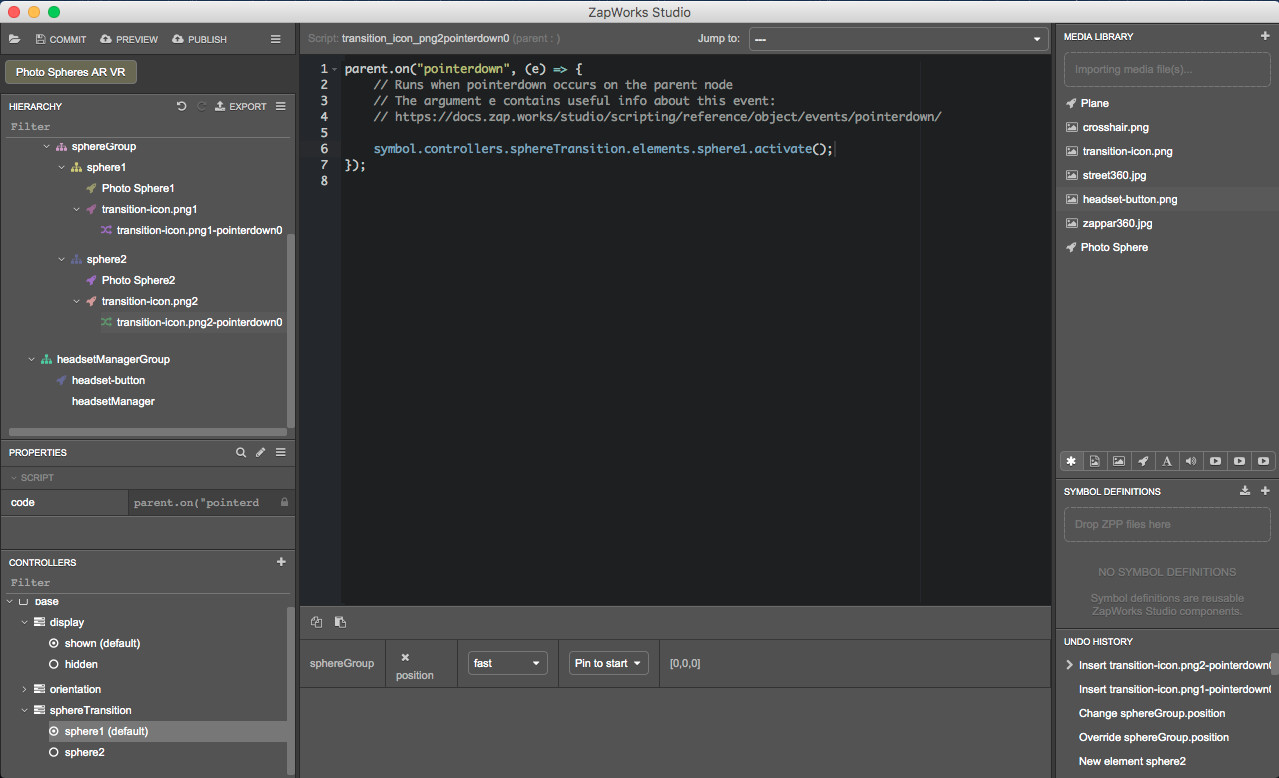
In the Hierarchy, in the ‘sphereGroup > sphere1’ node, right click on ‘transition-icon.png1’ and select ‘New > Script > pointerdown’.
Click and drag the ‘sphere2’ state from the Controllers panel into the pointerdown script, inside the function, and choose ‘activate’.
15.2) Set the icon to move from sphere 2 to sphere 1
We will now repeat this step to activate the ‘sphere1’ state from within the pointerdown script of the ‘transition-icon.png2’.
In the Hierarchy, within the 'sphereGroup > sphere2’ node, right click on ‘transition-icon.png2’ and select ‘New > Script > pointerdown’.
Click and drag the ‘sphere 1’ state from the Controllers panel into the pointerdown script, inside the function, and choose ‘activate’.
15.3) Set the headset button
To make sure you can see the changes you make in the Studio 3D view, in the Controllers panel select the ‘base’ controller and in the Hierarchy, select the ‘root’ node.
The special “base” entry in the Controllers panel returns the Studio to the default behavior where properties that haven’t been added to any controller can be modified.
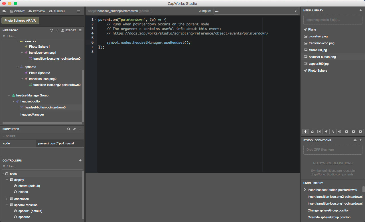
In the Hierarchy, within the ‘headsetManagerGroup’, right click on the ‘headset-button’ node and select ‘New > Script > pointerdown’.
Drag the ‘headsetManager’ from the Hierarchy into the pointerdown script, within the function and when releasing, select ‘useHeadset’.
15.4) Change the orientation of the headset button
We want the orientation of the headset button to be adjusted based on the orientation of the mobile device used to view the experience. To do so, we will need to use the ‘orientation’ controller.
In the Hierarchy, click on the ‘headset-button’ node. In the Controllers panel, select the ‘orientation > portrait’ state and change the ‘rotation’ property in the 'Transform’ section to (0,0,90).
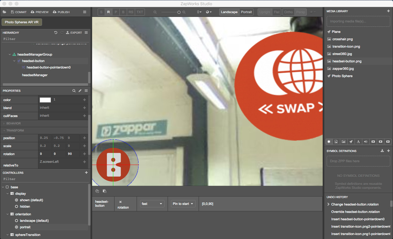
You can click on the landscape and portrait button at the top of the 3D view and select the corresponding orientation state in the Controllers panel to see how it will be displayed on a device’s screen.
16. Preview the experience
Click on the “Preview’ button and scan the zapcode with your device.
In addition to what you could see at the end of the previous part, you should now notice that:
- The headset button in the bottom left corner of the screen rotates depending on the orientation of the device;
- Pressing the headset button activates the headset view;
- Pressing the transition icon while in sphere 1 triggers the transition to sphere 2 and vice versa. However, this only works in the standard view.
Part 5: Setting up functionality in headset view
We'll define and set up the functionality in the headset view now.
In the standard view, we use the ‘transition-icons’ as buttons to move from one sphere to another. In the headset view, buttons can’t be used. The user can’t tap on a specific region of the screen since the latter is considered as a giant button.
To trigger an action while using the headset view, we can use an object called raycaster. We set a raycaster so that when it intersects with an object we’ve specified it triggers an action such as changing state or playing a timeline. Please, see the Raycasters article for more information.
A raycaster whose ‘relativeTo’ property is set to Z.camera can be thought of as an invisible straight line perpendicular to your mobile device and thus pointing in the direction you’re facing.
In this project, we will set the raycaster so that when it intersects with a transition icon the view moves to the other photosphere.
17. Add a raycaster group to the Hierarchy
In the Hierarchy, right click on the ‘content’ node, select ‘New > Group” and call it “raycasterGroup”.
17.1) Create the raycaster
To make sure you can see the content of the experience and changes you make, in the Controllers panel within the ‘sphereTransition’ controller, select ‘sphere1’. Then, click on ‘base’ and in the Hierarchy, select the ‘root’ node.
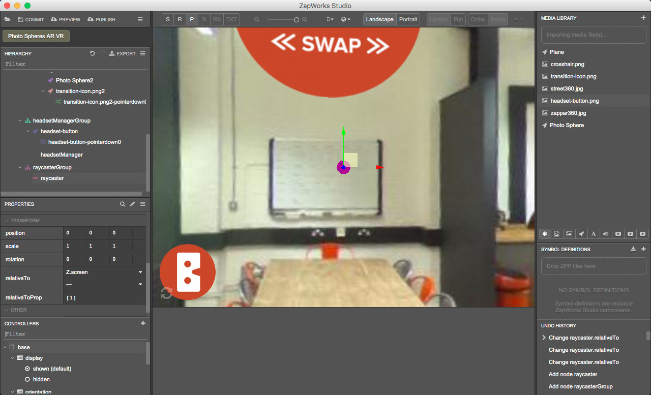
In the Hierarchy, right click on the ‘raycasterGroup’ node. Select ‘New > Raycaster’ and call it “raycaster”.
In the Properties panel, set the ‘relativeTo’ property in the ‘Transform’ section to ‘Z.screen’.
17.2) Create a colliderTag for the raycaster
With the ‘raycasterGroup’ node still selected in the Hierarchy, click on ‘raycaster’ and in the Properties panel, click on the down arrow next to the ‘colliderTag’ property in the 'Raycaster’ section and select ‘Create New Tag’. Name the colliderTag “sphereSwap”.
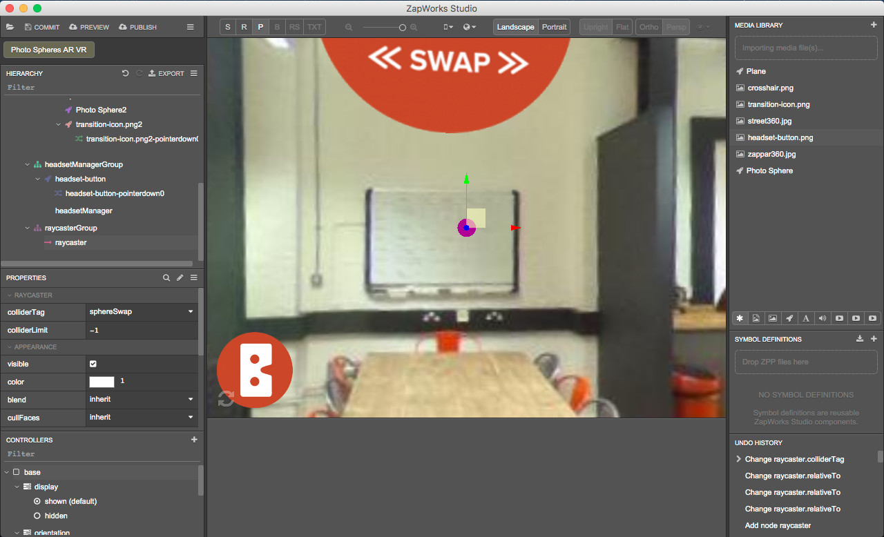
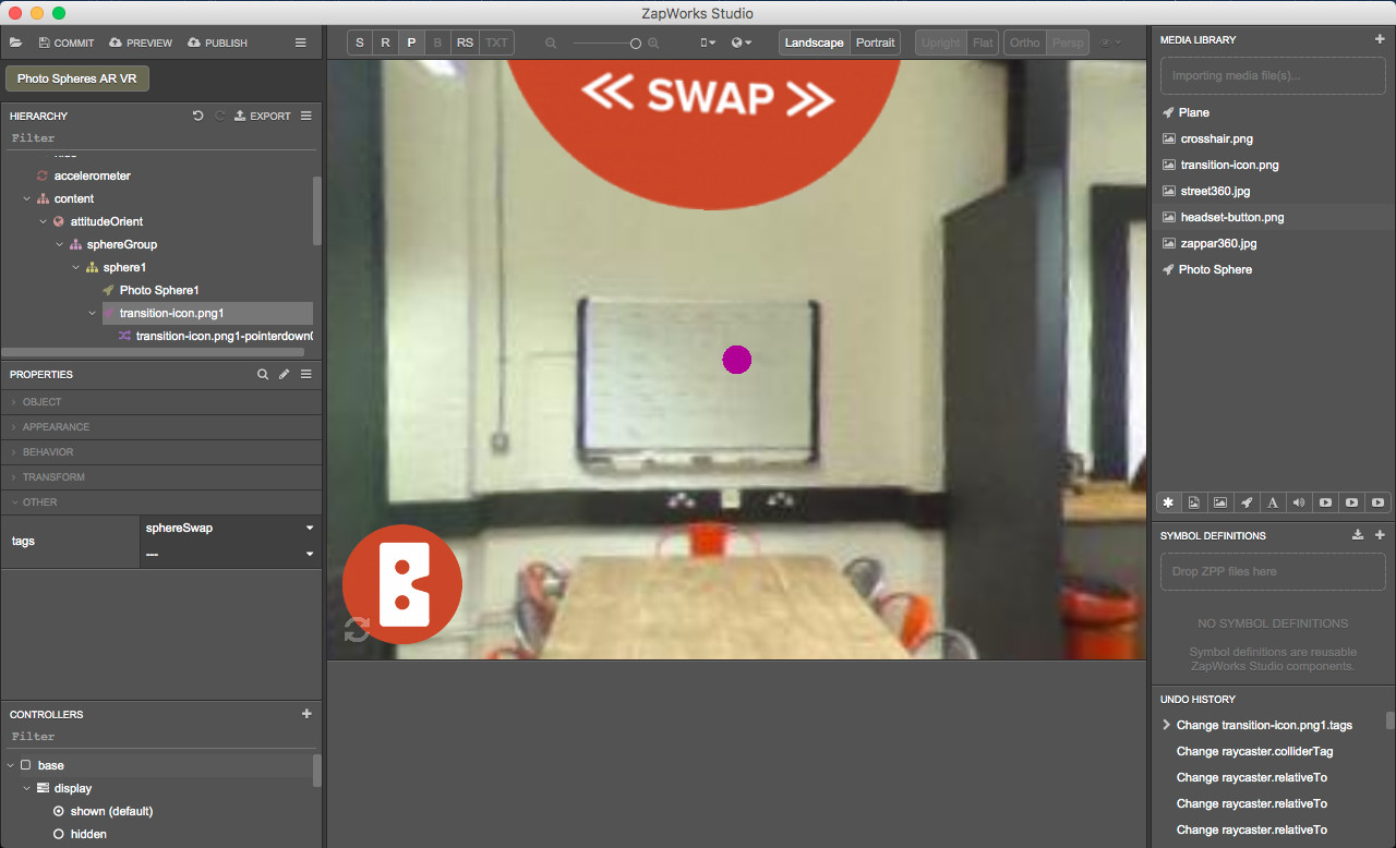
17.3) Add the colliderTag to the transition icons
Adding a raycaster’s colliderTag as the tag of an object will allow the raycaster to detect collisions with this object. In the Hierarchy, within the ‘sphereGroup > sphere1’ node, select the ‘transition-icon.png1’.
In the Properties panel click on the ‘tags’ property in the ‘Other’ section and select ‘sphereSwap’.
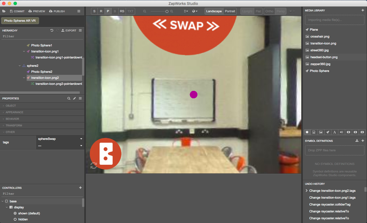
Select the ‘transition-icon.png2’ and again, in the Properties panel click on the ‘tags’ property in the ‘Other’ section and select ‘sphereSwap’.
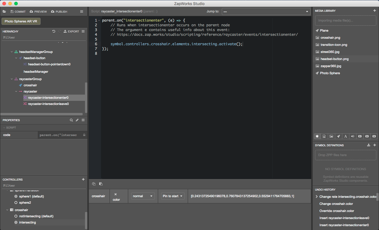
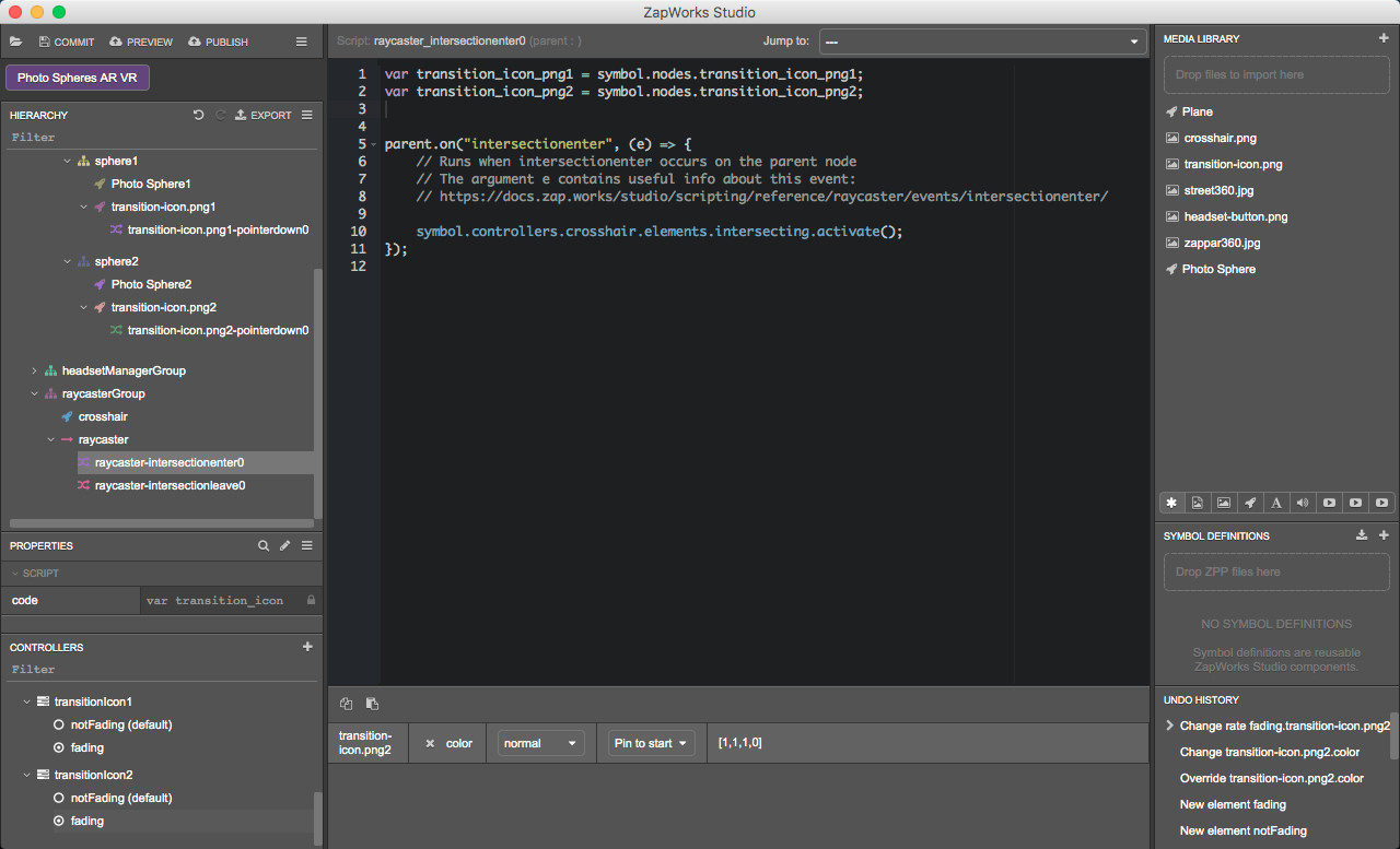
17.4) Add an intersection script for the raycaster
In the Hierarchy, right click on the ‘raycaster’ node and select ‘New > Script > intersectionenter’.
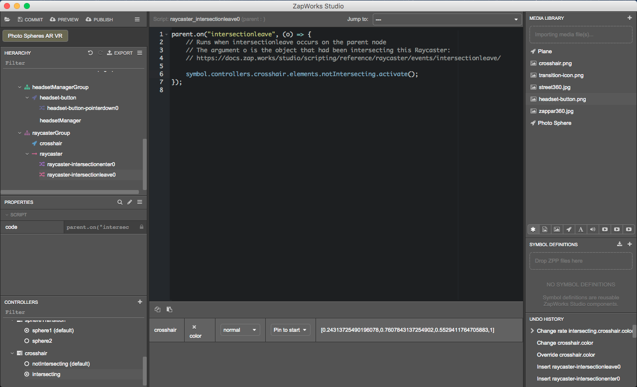
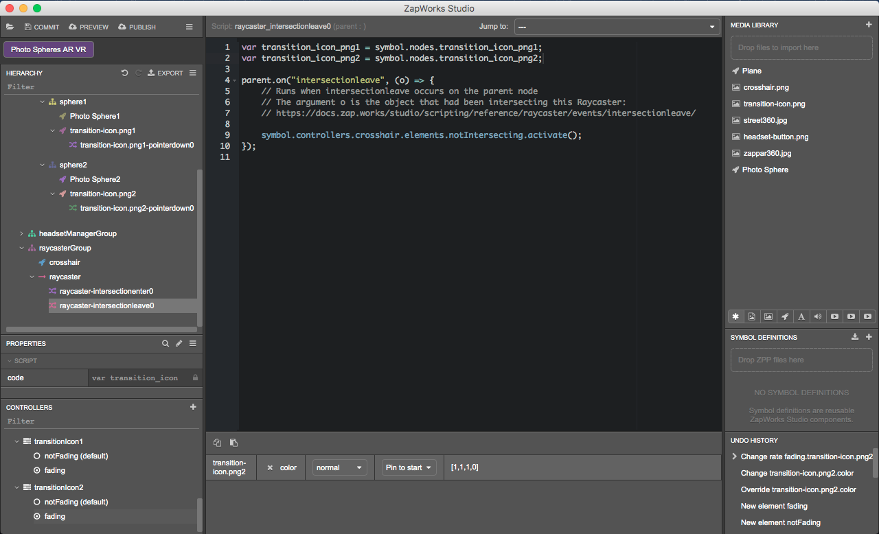
Again, right click on the ‘raycaster’ node but this time select ‘New > Script > intersectionleave’.
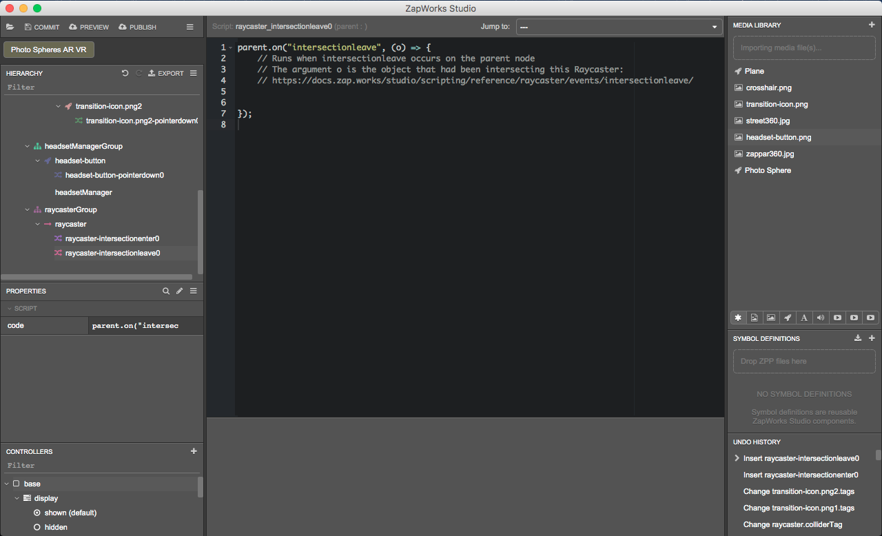
These two scripts will be used to activate states later on.
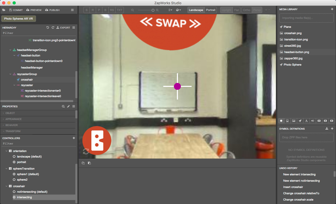
18. Add a crosshair for the raycasters
Since a raycaster is an invisible line, we’ve decided to use a crosshair to represent the raycaster and thus give the user an idea of the direction in which the raycaster is pointing.
Drag ‘crosshair.png’ from the Media Library into the Hierarchy, within the ‘raycasterGroup’ node, before or after the ‘raycaster’ node. Rename it to ‘crosshair’.
In the Properties panel:
- Make sure the ‘layerMode’ property in the 'Appearance’ section is set to ‘overlay’,
- Change the ‘scale’ property in the 'Transform’ section to (0.4, 0.4, 0),
- Change the ‘relativeTo’ property in the 'Transform’ section to ‘Z.screen’.

18.1) Create a controller for the crosshair
To show the user when the raycaster intersects with an icon, we‘ve decided to make the crosshair become green when it intersects with a ‘transition-icon’ object.
In the Controllers panel, click on the ‘+’ icon, select ‘New controller’ and call it “crosshair”.
18.2) Add states to the controller
Right-click on the ‘crosshair’ controller, select ‘New State’ and call it “notIntersecting”. Make sure it is set as the default state.
Right-click on the ‘crosshair’ controller, select “New state” and call it “intersecting”.
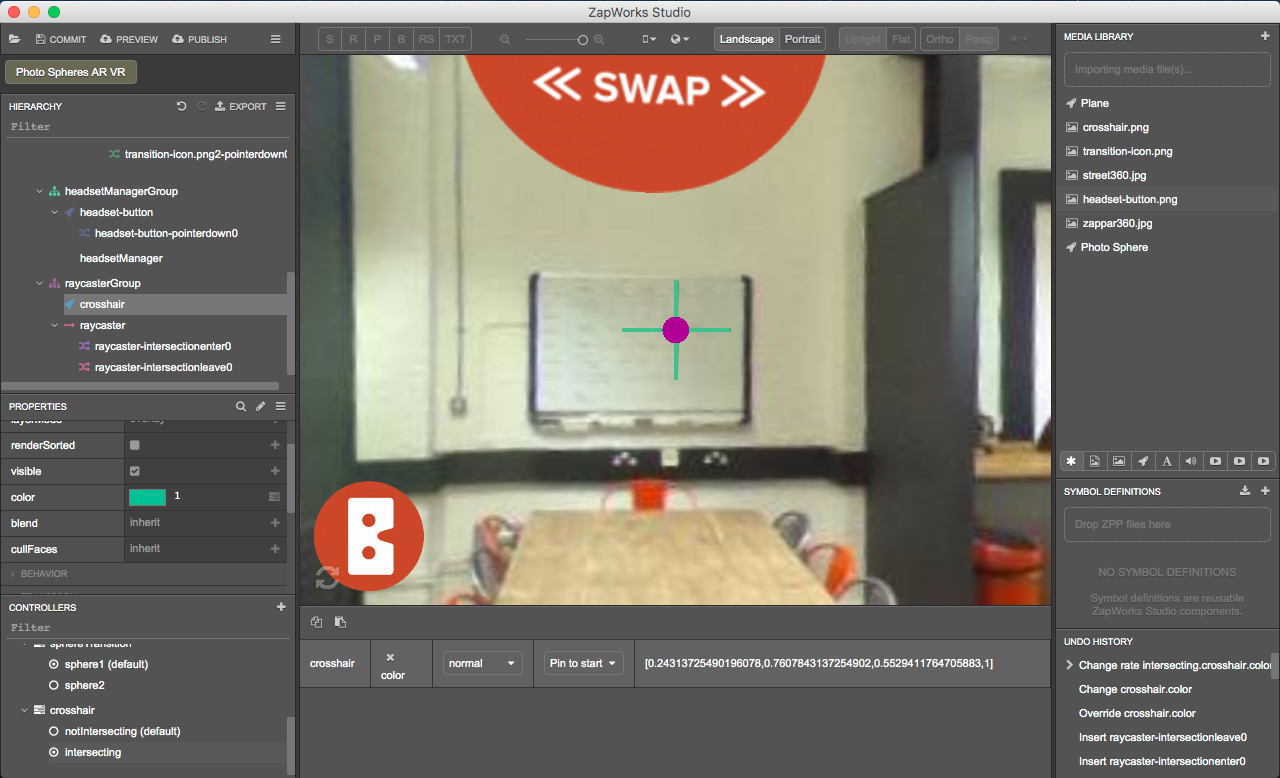
18.3) Add a property to the controller
In the Hierarchy, click on the ‘crosshair’ node and in the Controllers panel, select the ‘intersecting’ state.
In the Properties panel click on the ‘+’ icon next to the ‘color’ property in the ‘Appearance’ section to add this property to the ‘crosshair’ controller and click on the color box next to the ‘color’ property in the ‘Appearance’ section. Set the color to green, the HEX field should be set to “ff 3ec28d”.
In the state panel, set the transition speed to ‘normal’.
18.4) Activate the crosshair states
In the Hierarchy, open the raycaster’s intersectionenter script. Drag the ‘intersecting’ state from the Controllers panel into the script, within the function and choose 'activate'.
In the Hierarchy, open the raycaster’s intersectionleave script. Drag the ‘notIntersecting’ state from the Controllers panel into the script, within the function and choose 'activate'.
19. Preview the experience
Click on the “Preview’ button and scan the zapcode with your device.
Here is what you should see now in addition to what you could see at the end of the previous part:
- The crosshair appears in the middle of the screen,
- When it intersects with a transition icon, it becomes green.
Part 6: Animation for the transition between spheres in headset view
We are now looking to move to another sphere when the crosshair (and consequently the raycaster) intersects with an icon.
We could decide to move to the other sphere as soon as the raycaster points at the icon. However, this could be annoying for the user because if they made the raycaster cross the icon by mistake, it would immediately move to the other sphere.
That’s why we’ve decided to add a delay after the crosshair has started pointing at the icon and before moving to the other sphere. This way the user has 2 possibilities: they either hold the crosshair pointing at the icon to move to another sphere or move away from the icon to reverse the action and stay in the current sphere.
To do that in Studio, we will set the project so that when a raycaster is held pointing at a transition-icon the icon fades out. After 4 seconds, it fully vanishes and the user is taken to the center of sphere 2. If the user has moved the raycaster out of the transition-icon before reaching 4 seconds, the icon fully re-appears and the user is kept inside the current sphere.
20) Create a transition state for the crosshair
To make sure you see the content of the experience and changes you make, in the Controllers panel, make sure ‘sphereTransition > sphere1’ is selected and click on ‘base’. In the Hierarchy, click on the ‘root’ node to display the 3D view.
Using the widget in the bottom left of the 3D view, locate the icon in sphere 1.
20.1) Create a controller for the transition icon 1
In the Controllers panel, click on the ‘+’ icon, click on “New Controller” and name it “transitionIcon1”.
20.2) Add states to the controller
Right-click on the ‘transitionIcon1’ controller, select ‘New State’ and call it “notFading”.
Again, right click on the ‘transitionIcon1’ controller, select ‘New State’ and call it “fading”.
20.3) Set the ‘fading’ state
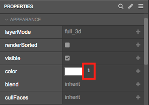
With the ‘fading’ state selected in the Controllers panel, click on the ‘transition-icon.png1’ in the Hierarchy. In the Properties panel, click on ‘+’ next to the ‘color’ property in the ‘Appearance section. Set the color transparency to 0.
To change the transparency of an object, you simply need to change the number next to the color box in the Properties panel and set its value to anything between 0 (0% - the object can’t be seen) and 1 (100% - the object is fully opaque).
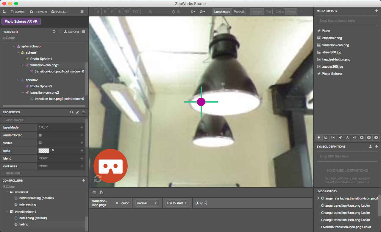
To see how the icon fades out in ‘Photo Sphere1’, you can take a look at the 3D view and click on the 2 states you’ve just created.
20.4) Create a controller for the transition icon 2
To see the inside of sphere 2, in the Controllers panel select ‘sphereTransition > sphere2’ and locate the transition icon.
In the Controllers panel, click on the ‘+’ icon, click on “New Controller” and name it “transitionIcon2”.
20.5) Add states to the controller
Right-click on the ‘transitionIcon2’ controller, select ‘New State’ and call it “notFading”.
Again, right click on the ‘transitionIcon2’ controller, select ‘New State’ and call it “fading”.
20.6) Set the ‘fading’ state
With the ‘fading’ state selected in the Controllers panel, click on the ‘transition-icon.png2’ in the Hierarchy. In the Properties panel, click on ‘+’ next to the ‘color’ property in the ‘Appearance section. Set the color transparency to 0.
In the state panel, change the transition speed from ‘fast’ to ‘normal’.
To see how the icon fades out in sphere 2, you can take a look at the 3D view and click on the 2 states you’ve just created!
21. Set the states to activate in the raycaster’s scripts
If the raycaster intersects with the transition icon in sphere 1, the icon fades out until fully vanishing. When the icon has vanished, we move to sphere 2.
If the raycaster stops intersecting with a transition icon before it has fully vanished, the icon fully re-appears and we stay in the current sphere.
As there is 1 raycaster and 2 icons, we will need to check what icon the raycaster is intersecting with, to make sure that only this icon vanishes.
21.1) Add the icons as variables in the raycaster’s scripts
Click on the raycaster’s intersectionenter script to open it.
Drag ‘transition-icon.png1’ and ‘transition-icon.png2’ from the Hierarchy into the script, at the top, above the function. When releasing, select ‘Insert local variable’.
Click on the raycaster’s intersectionleave script to open it.
Drag ‘transition-icon.png1’ and ‘transition-icon.png2’ from the Hierarchy into the script, at the top, above the function. When releasing, select ‘Insert local variable’.
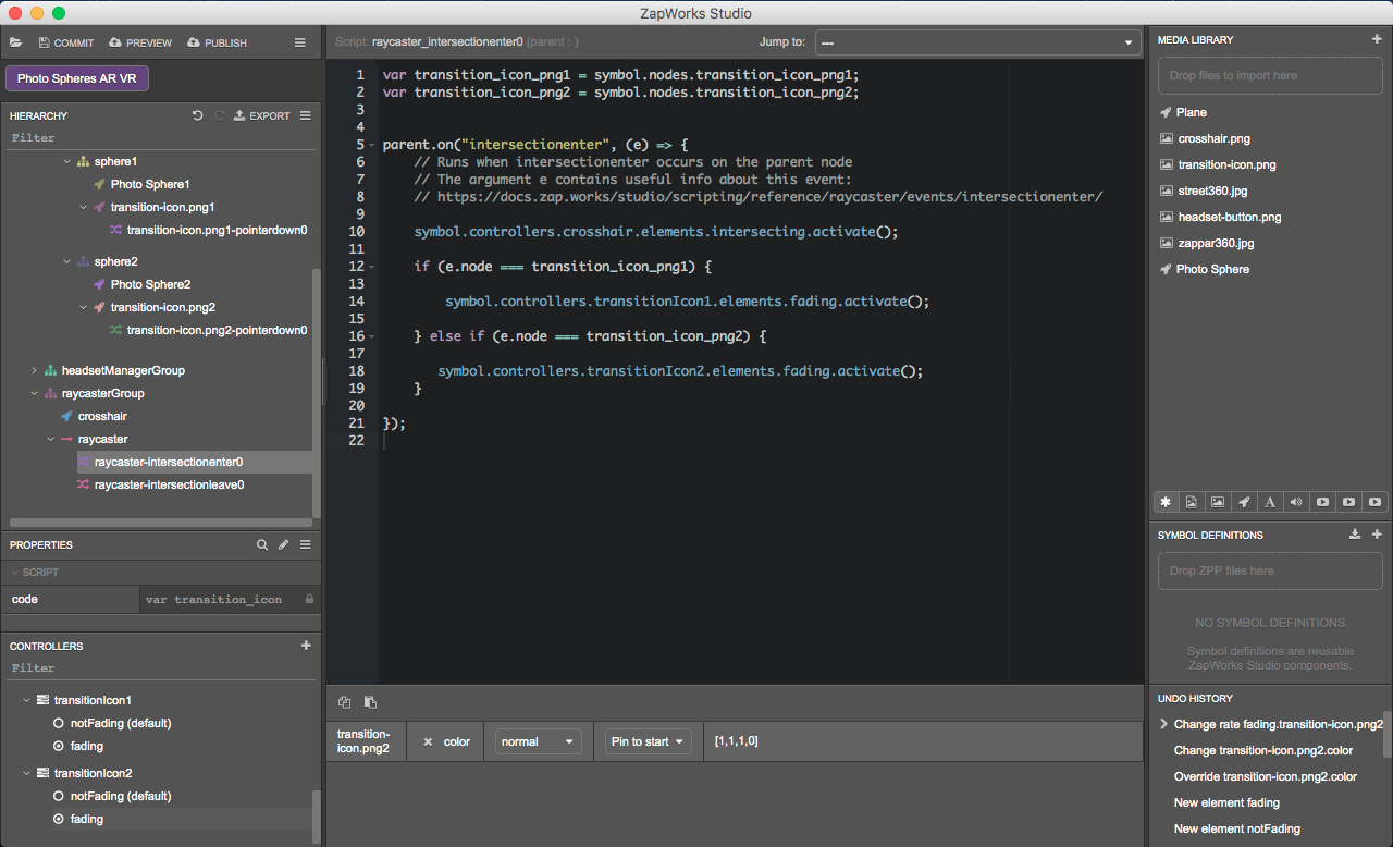
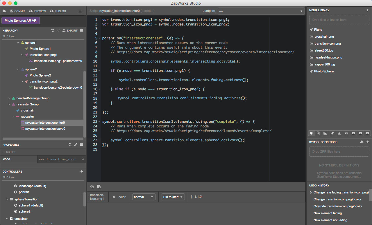
21.2) Activate the transition icons’ fading states within the raycaster’s intersectionenter script
Now, we need to activate the fading state for one transition icon or the other depending on the value of the node returned by the intersectionEvent:
If the raycaster intersects with ‘transition-icon.png1’, the ‘transitionIcon1 > fading’ state will be activated. Else, if the raycaster intersects with ‘transition-icon.png2’, the ‘transitionIcon2 > fading’ state will be activated.
For more information please, see the intersectionEvent documentation.
We will use an if statement to test the value of the object the raycaster is intersecting with.
Open the raycaster’s intersectionenter script and add the following if statement inside the ‘intersectionenter function’:
if (e.node === transition_icon_png1) {

} else if (e.node === transition_icon_png2) {

}
Drag the ‘transitionIcon1 > fading’ state from the Controllers panel into the script, within the first pair of curly brackets of the if statement. When releasing, set the state to activate.
Drag the ‘transitionIcon2 > fading’ state into the script, within the second pair of curly brackets of the if statement. When releasing, set the state to activate.
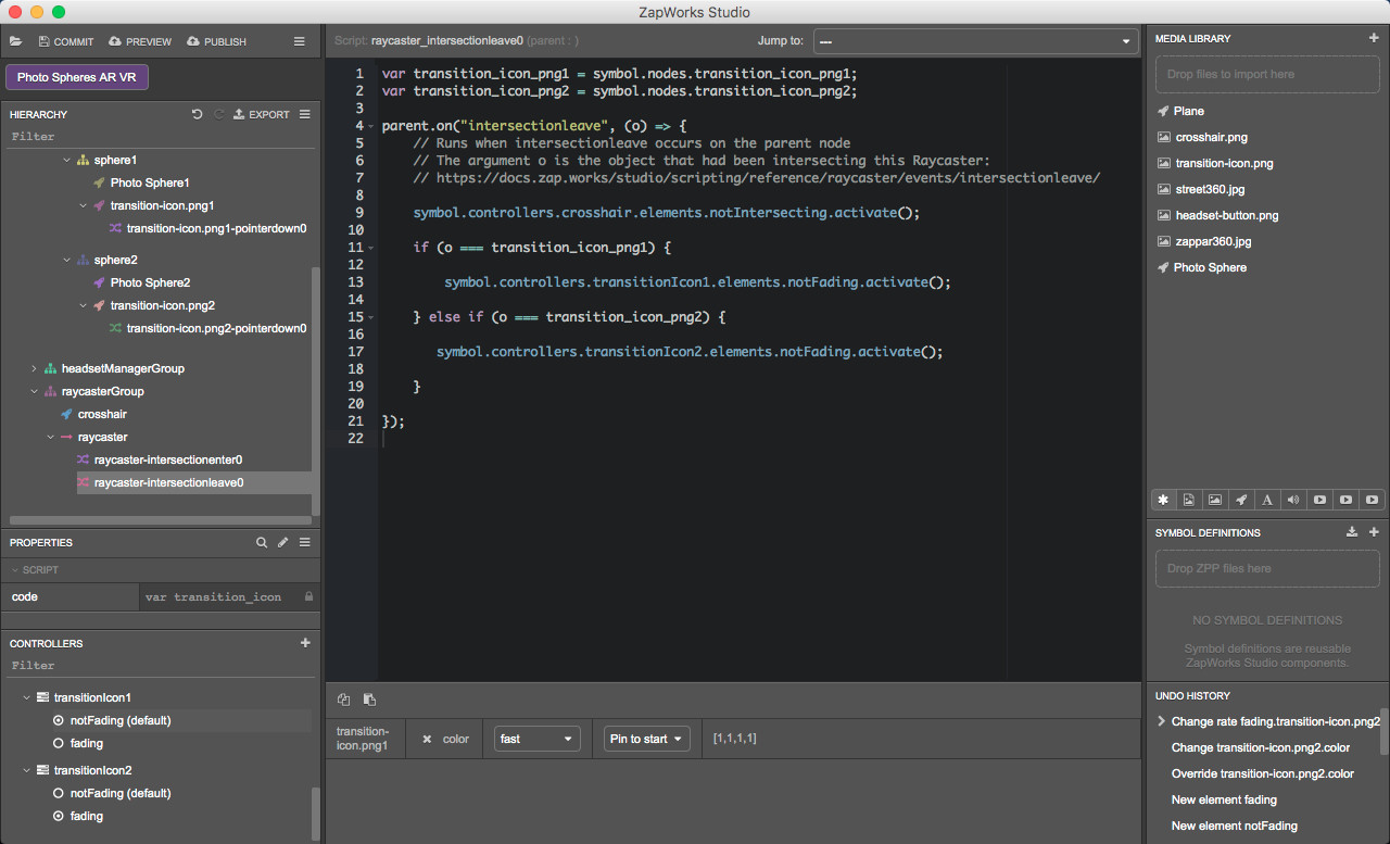
21.3) Activate the transition icons’ ‘notFading’ states
Depending on the object the raycaster was intersecting with before leaving the intersection, we will need to activate the notFading state of one transition icon or the other. Again, we will need to use an if statement to test the value of the object (transition icon).
When the intersectionleave event is fired, attached handler functions are called with a single argument, the Z.Object node it was intersecting. Please, see the intsersectionLeave article for more information.
Open the raycaster’s intersectionleave script.
Within the intersectionleave function, add the following statement:
if (o === transition_icon_png1) {

} else if (o === transition_icon_png2) {

}
Drag the ‘transitionIcon1 > notFading’ state into the script, within the first pair of curly brackets of the if statement. When releasing, set the state to activate.
Drag the ‘transitionIcon2 > notFading’ state into the script, within the second pair of curly brackets of the if statement. When releasing, set the state to activate.
22. Transition between the two spheres
We will now set the transition from one sphere to the other to happen after the transition icon in the current sphere has fully vanished.
22.1) Transitioning from sphere 1 to sphere 2
In the Hierarchy, open the raycaster’s intersectionenter script.
Drag the ‘transitionIcon1 > fading’ state into the script, outside and under the intersectionenter function. When releasing select ‘Add an event handler > complete’.
Drag the ‘sphereTransition > sphere2’ state into the script, within the ‘transitionIcon1 fading ‘on complete’ function. When releasing, set the state to activate.
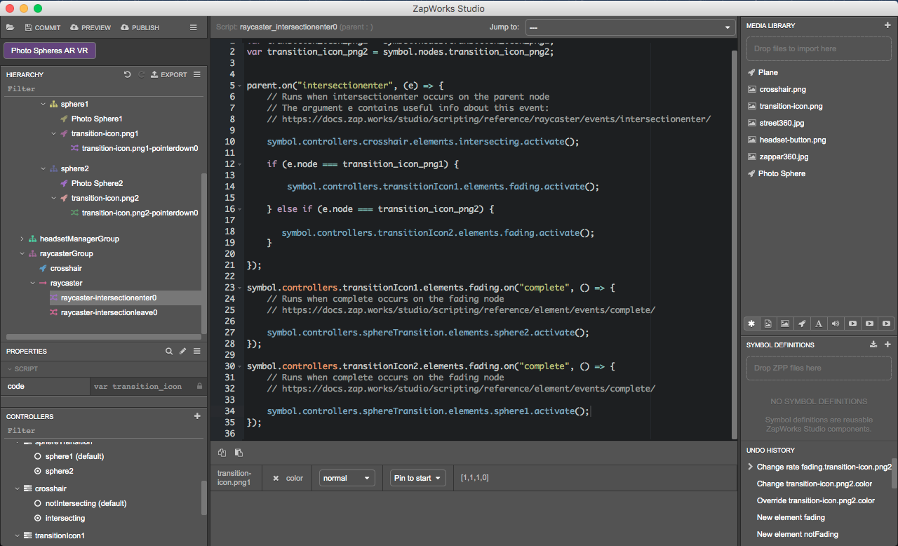
22.2) Transition from sphere 2 to sphere 1
In the Hierarchy, with the raycaster’s intersectionenter script still open, drag the ‘transitionIcon2 > fading’ state into the script, outside and under the ‘transitionIcon1’ fading ‘on complete’ function. When releasing select ‘Add an event handler > complete’.
Drag the ‘sphereTransition > sphere1’ state into the script, within the ‘transitionIcon2 fading on complete’ function. When releasing, set the state to activate.
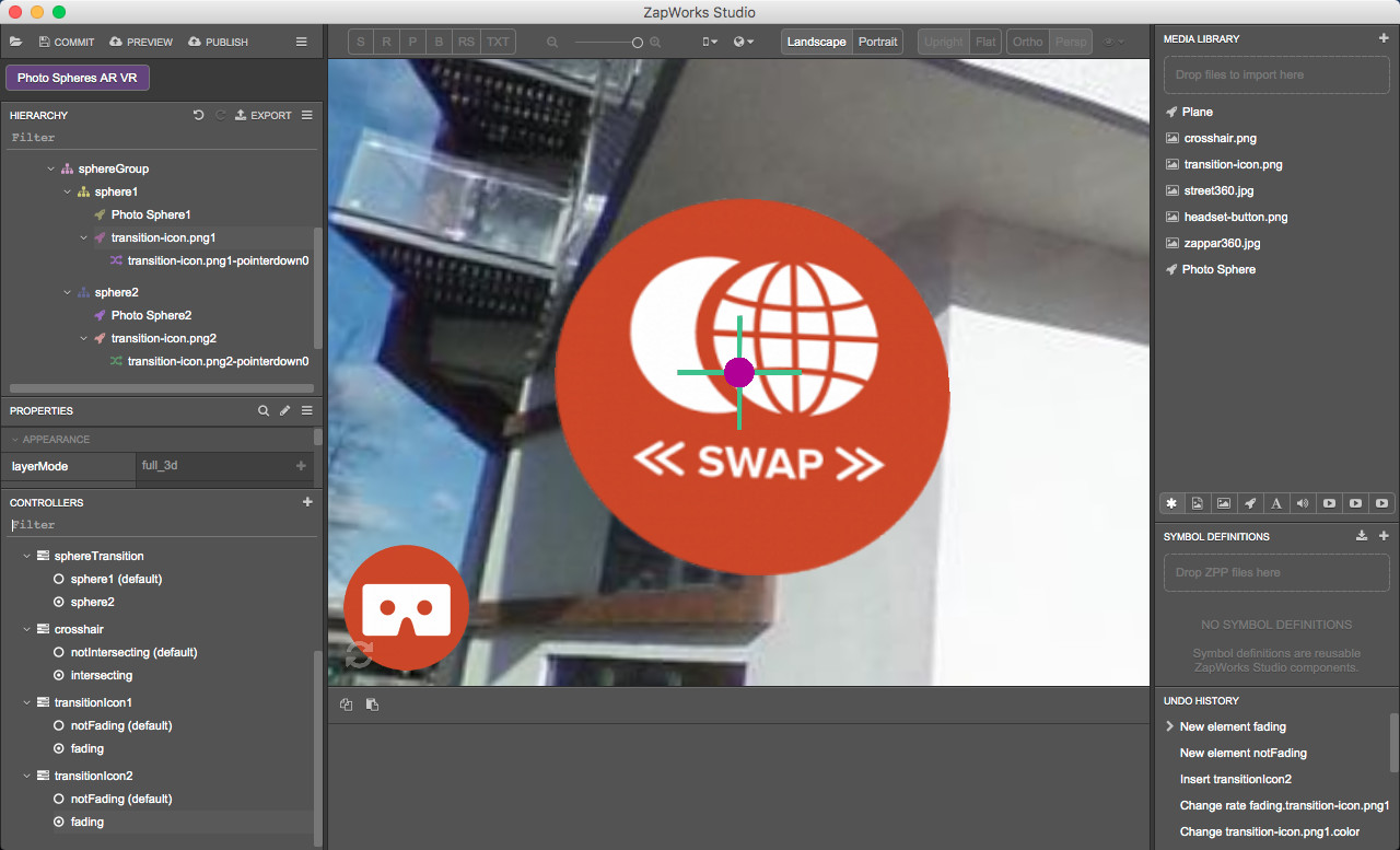
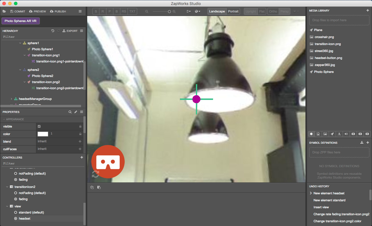
23. Preview the experience
Click on the “Preview’ button and scan the zapcode with your device.
In addition to what you could see at the end of the previous part, you should now see that by pointing at the icon with the crosshair, the transition icon fades out. If you stop pointing at it before it has fully vanished, the icon re-appear while if you’re holding the crosshair on it, it fully vanishes and the camera moves to the center of the other photosphere.
Part 7: Hide/show content in standard and headset views
We don’t want the content that is meant to be available in the headset view only to show up in the standard view and vice versa.
The headset button should be hidden in the headset view as the crosshair should be hidden when in standard view. We’ll then create a new controller and two states, one for the standard view and one for the headset view.
24. Create a controller for the view
To make sure you see the content of the experience and the changes you make, in the Controllers panel select ‘sphereTransition > sphere1’ and click on ‘base’. In the Hierarchy, select the ‘root’ node.
In the Controllers panel, click on the ‘+’ icon, select ‘New Controller’ and call it “view”.
24.1) Add a state for the standard and headset views
Right click on ‘view’, select ‘New State’ and call it “standard”. Make sure this is the default state.
Right click on ‘view’, select ‘New State’ and call it “headset”.
24.2) Add properties to the controller
Select the ‘standard’ controller in the Controllers panel.
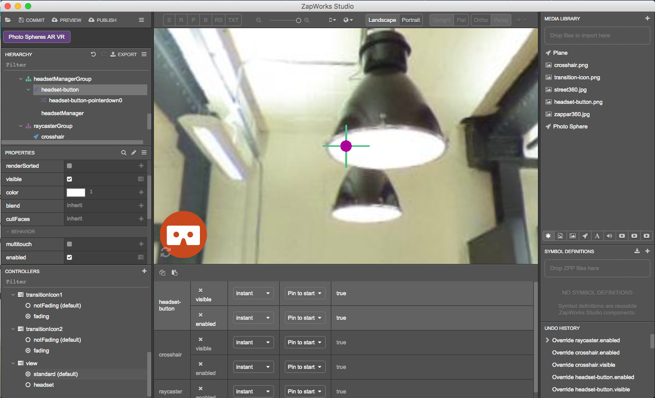
In the Hierarchy select the ‘headsetManagerGroup > headset-button’. In the Properties panel, click on the ‘+’ icon next to:
- ‘Appearance > visible’
- ‘Behavior > enabled’.
In the Hierarchy select the 'raycasterGroup > crosshair’ node. In the Properties panel, click on the ‘+’ icon next to:
- ‘Appearance > visible’
- ‘Behavior > enabled’.
In the Hierarchy select the ‘raycasterGroup > raycaster’ node. In the Properties panel, click on the ‘+’ icon next to ‘Behavior > enabled’.
24.3) Display or hide the headset button
The headset button should be available in the standard view only.
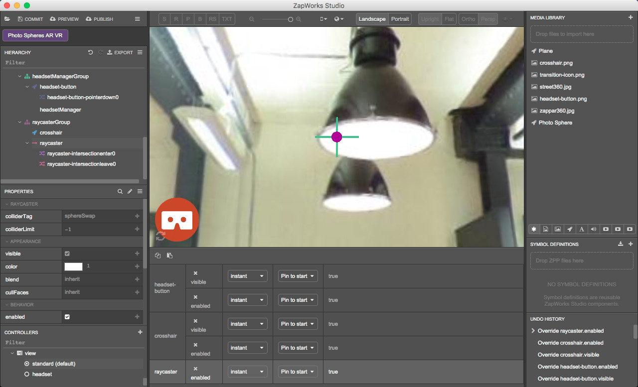
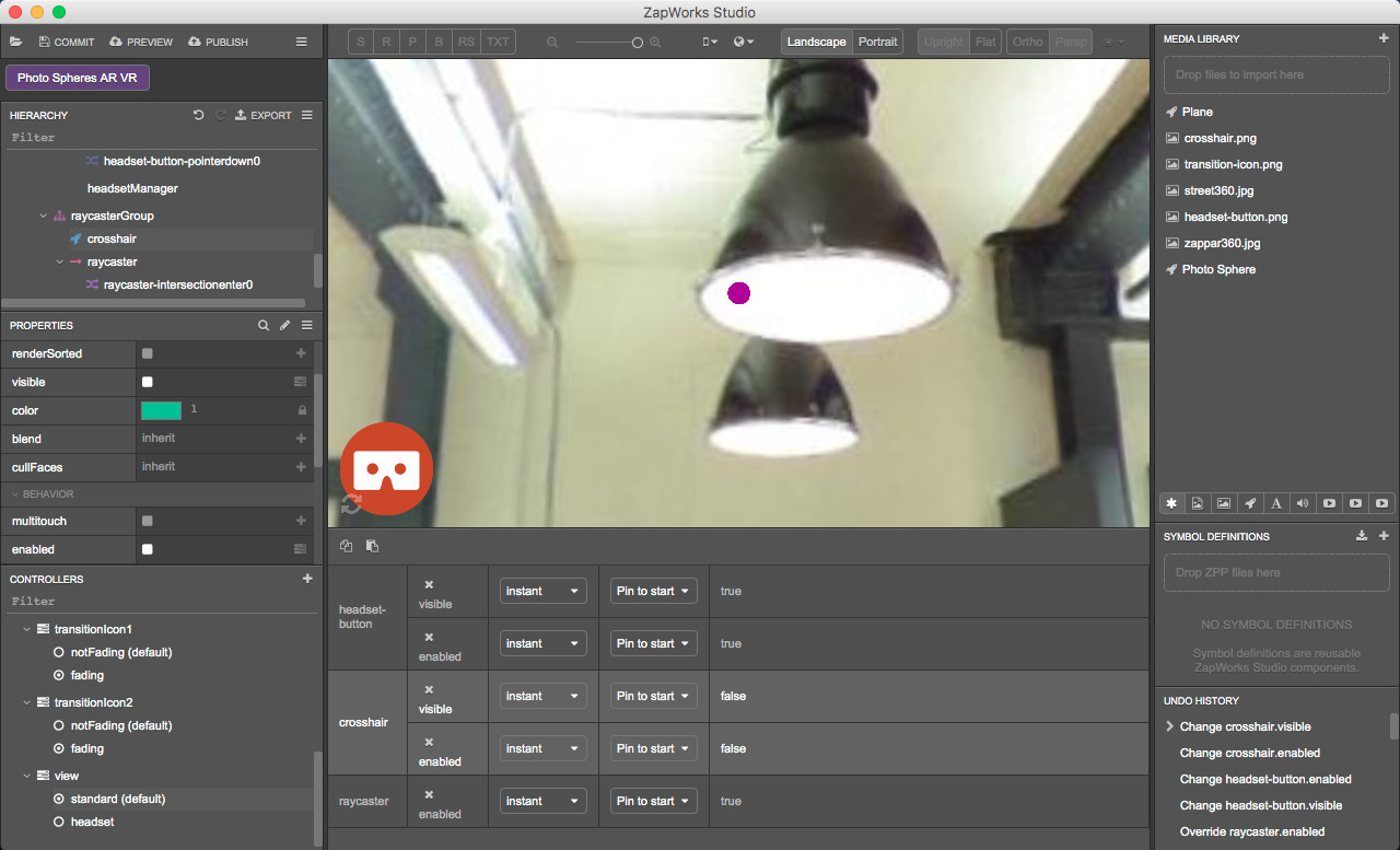
With the ‘headset-button’ node still selected in the Hierarchy, click on the ‘view > standard’ state in the Controllers panel and make sure the box is checked for both:
- The ‘visible’ property in the ‘Appearance’ section,
- The ‘enabled’ property in the ‘Behavior’ section.
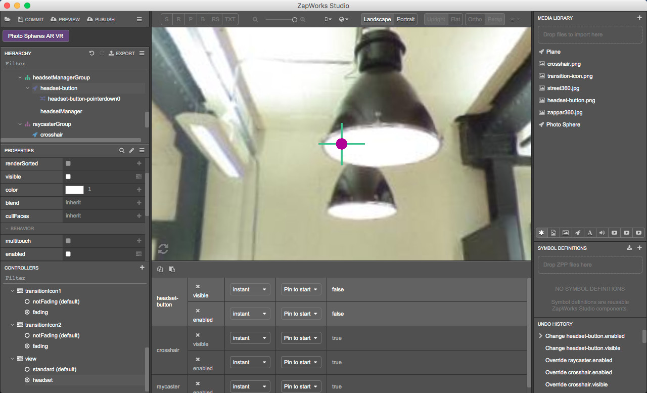
Now select the ‘view > headset’ state in the Controllers panel and uncheck the boxes for both:
- The ‘visible’ property in the ‘Appearance’ section,
- The ‘enabled’ property in the ‘Behavior’ section.
24.4) Hide or display the crosshair
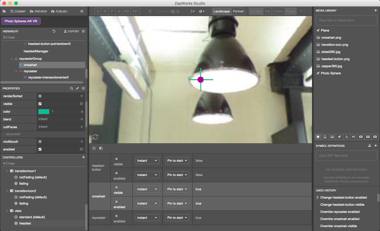
The crosshair should only be visible and enabled in the headset view.
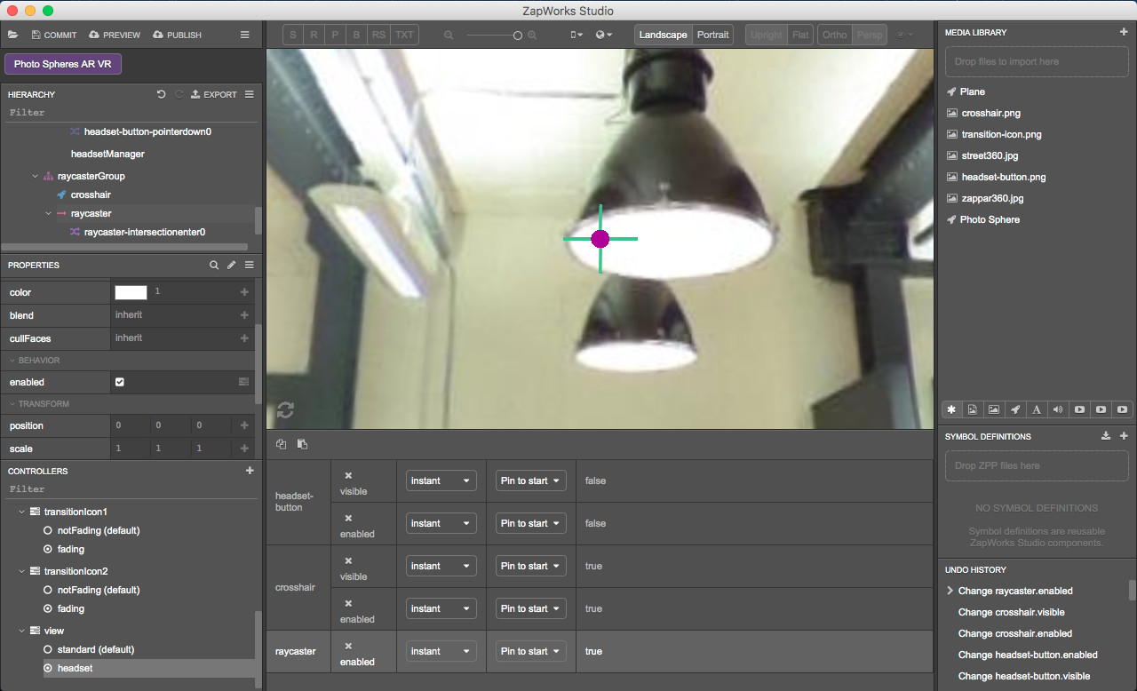
With the ‘view > headset’ still selected in the Controllers panel, in the Hierarchy select the 'raycasterGroup > crosshair’ node. In the Properties panel, make sure both boxes are checked for:
- 'Appearance > visible’
- ‘Behavior > enabled’.
With the ‘crosshair’ node still selected in the Hierarchy, click on the ‘view > standard’ in the Controllers panel. In the Properties panel, uncheck both boxes for:
- ‘Appearance > visible’
- ‘Behavior > enabled’.
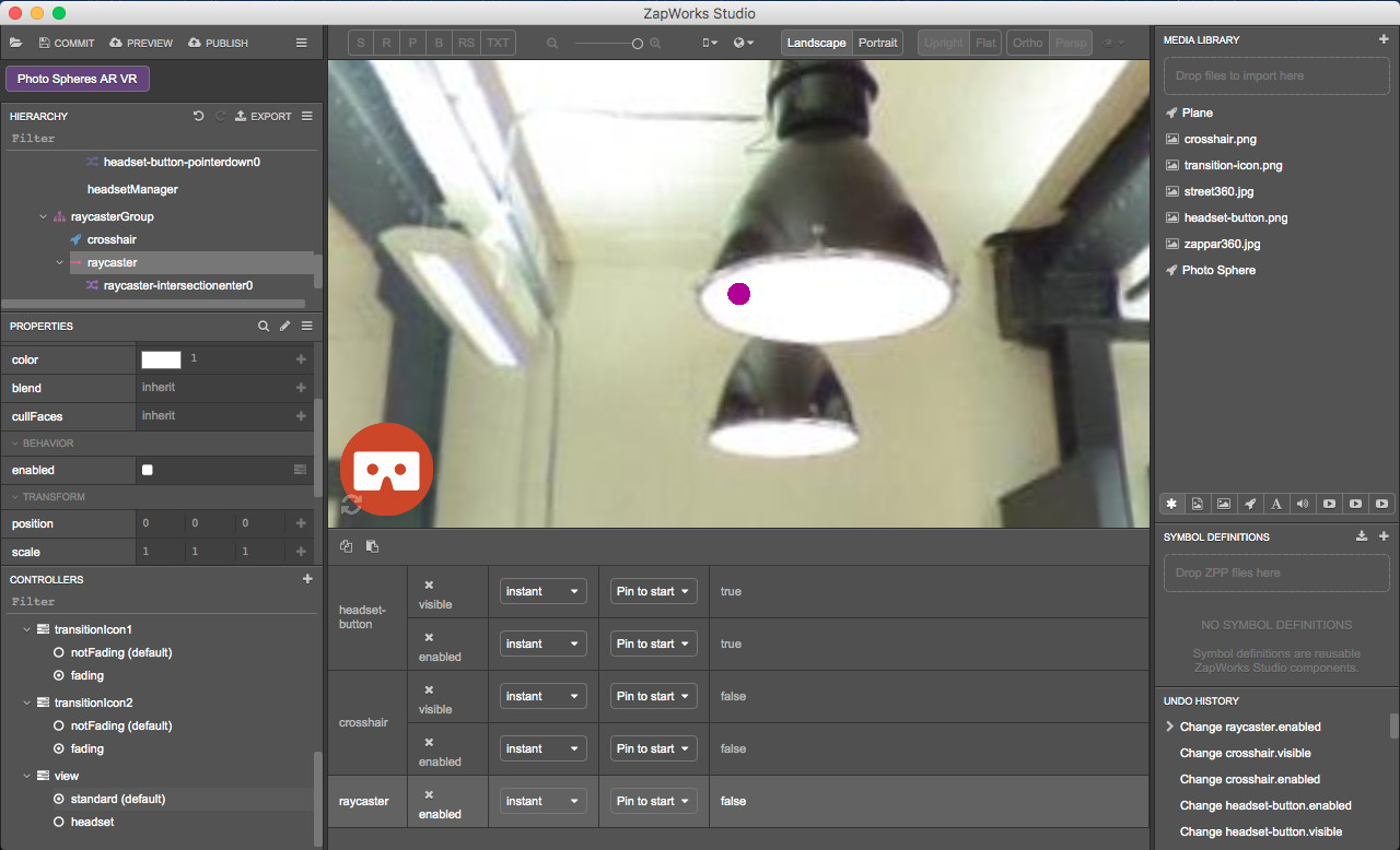
24.5) Disable or enable the raycaster
The raycaster is used in headset view only and should be disabled in standard view.
With the ‘view > standard’ still selected, click on the 'raycasterGroup > raycaster’ node in the Hierarchy. In the Properties panel, uncheck the box next to ‘Behavior > enabled’.
With the ‘crosshair’ node still selected in the Hierarchy, click on the ‘view > headset’ state in the Controllers panel. In the Properties panel, make sure the box is checked for ‘Behavior > enabled’.
25. Activate the headset view
The headset view should be available as soon as the VR mode has been entered.
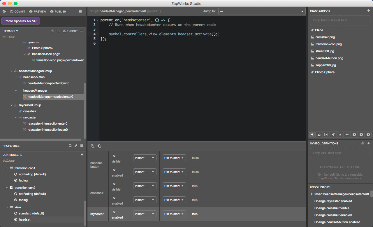
In the Hierarchy, within the ‘headsetManagerGroup’, right click on the ‘headsetManager’ node and select ‘New > Script > headsetenter’.
In the Hierarchy, in the ‘headsetManagerGroup > headsetManager’, open the headsetenter script.
Drag the ‘view > headset’ state from the Controllers panel into the headsetenter script, within the function. When releasing, select ‘activate’.
26. Activate the standard view
The standard view should be available when the user leaves the headset mode.
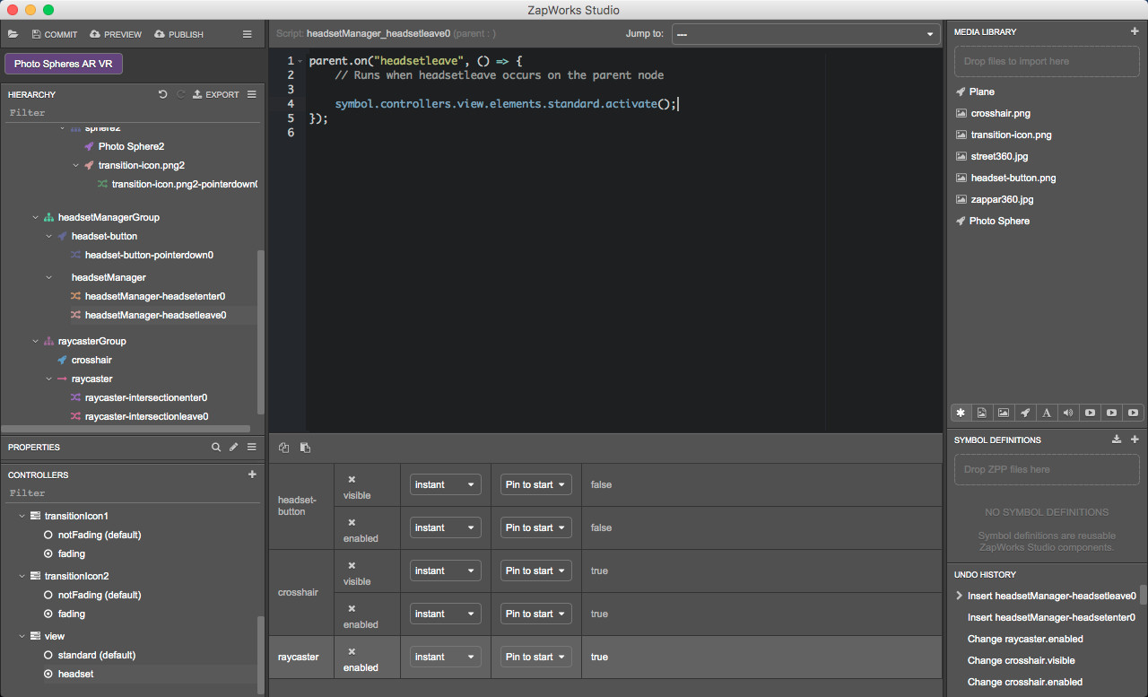
In the Hierarchy, within the ‘headsetManagerGroup’, right click on the ‘headsetManager’ node and select ‘New > Script > headsetleave’.
Drag the ‘standard’ state from the Controllers panel into the headsetManager’s headsetleave script, within the function and select ‘activate’.
27. Preview the experience
Click on the “Preview’ button and scan the zapcode with your device to see what the project you’ve just completed looks like!
Publish your experience to your Zapcode
It’s high time you published your project! hit ‘Publish’ in the top left corner to publish it to your previously created zapcode.
Choose the Zapcode that you created in the first step.
Congratulations!
That’s it. You have completed all the steps in this tutorial and created your own multiple photosphere experience. You are well on your way to mastering ZapWorks Studio. Nice!
Suggested Next Steps
- Add a third photosphere or even more and transition to those.
- Start with an experience tracked to an image then trasition to the photoshperes.
- Add sounds and other interactive elements.
Further Reading
To learn more about the concepts covered in this tutorial, please see the following pages:
- Gyro-oriented Environments - More information on Gyro-oriented experiences.
- Raycaster Overview - An overview of how to use raycasters.
- Headset Overview - An overview of how to use the headset mode.